Run in stand/dyno build.

Intlwaters

Help Support Intlwaters:

This site may earn a commission from merchant affiliate links, including eBay, Amazon, and others.
Got some runs in today, friggin' cold, only about 48*F. Had a hard time getting enough heat in the motor, havta figure out a better way to regulate it. Good news is the CPU cooler definitely puts out enough. Only saw about 150F on the IR gun, Nova Rossi runs in at 320.

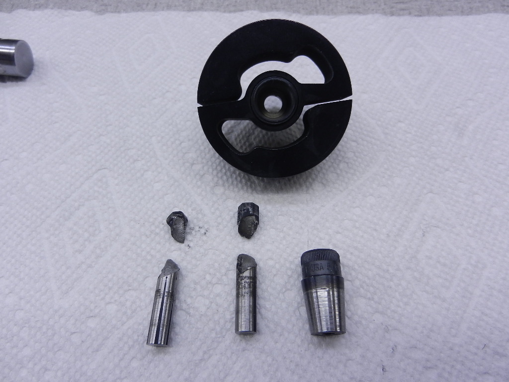
Broke a ball hex key, substituted a full hex that worked for a few runs then broke that. Think they're too hard. Might need a universal joint in there (thanks Jim!).

Pretty happy so far, got a gallon through this piston/sleeve and it's no where near ready to go fast yet, lol.

Left my plug wrench at home! 😁


Last edited:
Got some runs in today, friggin' cold, only about 48*F. Had a hard time getting enough heat in the motor, havta figure out a better way to regulate it. Good news is the CPU cooler definitely puts out enough. Only saw about 150F on the IR gun, Nova Rossi runs in at 320.

Broke a ball hex key, substituted a full hex that worked for a few run then broke that. Think they're too hard. Might need a universal joint in there (thanks Jim!).

Pretty happy so far, got a gallon through this piston/sleeve and it's no where near ready to go fast yet.

Left my plug wrench at home! 😁


Terry, before the days of Bondus ball drivers we made our own using a die grinder with mounted wheels. I think if you did a slight ball leaving plenty of meat where it broke you’d be fine. Just use a good name brand hex to start and grind slowly to not over heat
 
Thanks John, seems the hex idea creates a lot of heat too. The screw head and collet look like they've been heated with a torch!

Talking to my Consiellere I think I'm gonna make a universal but with a straight round end instead of a ball. We figured a ball isn't needed since the motor is aligned to the shaft, I'll just leave some clearance for heat expansion. Probably use a 1/8" dowel pin to drive it and will have to harden the female collet part. Not sure what material to use yet, something already fairly hard or something easily heat treated.

Here's the broken allen wrenches, they look brittle...


full
 
Terry,

Do you remember what I told you would happen if you attempted to use anything that resembled a HEX. Imagine how long a hex would survive at 7 HP+, turning 30,000 RPM+. The reason this happens can easily be shown with the diagrams I sent to you showing where the torque force is applied with a hex compared to a spline. Think about the very reliable ball & pin type universals CMB used on their larger size engines.
 

Attachments

  • torque%20cradle%20009.jpg
    torque%20cradle%20009.jpg
    70.1 KB · Views: 57
Terry, your build shows a quality that few people appreciate in this country these days. Sixty years ago this level of manufacturing was routine in the tool and die shops in the small town where I lived.

We tested a lot of engines other than Zenoahs and Quickdraws. The dyno was very good at uncovering weaknesses. Below are some tests we did for Tower on engines for their Rio. We also uncovered manufacturing flaws in the CMB 35. All these engines seemed to run well in boats. Zenoahs and Chung Yang engines were reasonably durable and that has been born out to this day. We also tested 3 - 11 cc (67) nitro engines; two CMBs and my K 67. None survived even one dyno run. They all suffered melted pistons. I believe this was because the dyno wheel put a larger load on the engines than the 1/8 scale boats they ran in. All were on the edge of detonation and it only took a little more to put them over the edge.

That's the main reason I don't recommend your large flywheel. Even our 5" flywheel was too much. The only person I know of who has tested 11 cc (67) size engines is Marty Davis. I could only find his flywheel sizes for 7.5 cc (45) engines. They used a 3 3/4" diameter flywheel for those engines.

Lohring Miller
 

Attachments

  • Fugi 27 Engine Tests.pdf
    350.1 KB · Views: 21
  • GW 261 Engine Report.pdf
    1.5 MB · Views: 14
Terry,

Do you remember what I told you would happen if you attempted to use anything that resembled a HEX. Imagine how long a hex would survive at 7 HP+, turning 30,000 RPM+. The reason this happens can easily be shown with the diagrams I sent to you showing where the torque force is applied with a hex compared to a spline. Think about the very reliable ball & pin type universals CMB used on their larger size engines.


Yup, you were absolutely right there Jim. I'm going to make a u joint from S7 and heat treat it to near 60Rc. Was planning to use a 1/8" dowel pin to drive it, think this would work?


Terry,

Have you looked into something like this?

https://www.mcmaster.com/flexible-s...alignment-precision-flexible-shaft-couplings/
Or..

https://www.mcmaster.com/flexible-shaft-couplings/constant-velocity-single-u-joints/
Thanks. Brad.
Titan Racing Components
BlackJack Hydros
Model Machine and Precision LLC


Looked at those and other couplers early on and based on other's experience and my own hunches decided to go with solid connections as much as possible, that's why I had to align the shaft and motor so accurately. Even if they did hold up I havta wonder how much power is absorbed by any kind of "soft" coupler?


Terry, your build shows a quality that few people appreciate in this country these days. Sixty years ago this level of manufacturing was routine in the tool and die shops in the small town where I lived.

We tested a lot of engines other than Zenoahs and Quickdraws. The dyno was very good at uncovering weaknesses. Below are some tests we did for Tower on engines for their Rio. We also uncovered manufacturing flaws in the CMB 35. All these engines seemed to run well in boats. Zenoahs and Chung Yang engines were reasonably durable and that has been born out to this day. We also tested 3 - 11 cc (67) nitro engines; two CMBs and my K 67. None survived even one dyno run. They all suffered melted pistons. I believe this was because the dyno wheel put a larger load on the engines than the 1/8 scale boats they ran in. All were on the edge of detonation and it only took a little more to put them over the edge.

That's the main reason I don't recommend your large flywheel. Even our 5" flywheel was too much. The only person I know of who has tested 11 cc (67) size engines is Marty Davis. I could only find his flywheel sizes for 7.5 cc (45) engines. They used a 3 3/4" diameter flywheel for those engines.

Lohring Miller


Not sure if it's deserved but thanks for the compliment anyway. It's sad what's happened to the tool and die and manufacturing trades.

I post this stuff mainly cause I hope guys find it interesting but also to draw on the experience and knowledge you guys all have, I use a lot of it!

You sure are right that weaknesses are uncovered, I think I'm gonna learn a lot about how these things operate. I'm lucky in a way that I'm testing with the fan for now, that way I can work stuff out before I start melting pistons, lol!

You're probably right about the wheel size, my buddy Mikey Ross says the same, he blew up a handful of Zens with is original chain driven 10" x 5" 45lb wheel.

I sure see how you guys twisted up that 1/4" key stock...
 
Terry,

Then you'll probably have to go with SOLID connections, foregoing any attempts at any coupler altogether. If you're breaking parts with just the fan as a dampener, something heavier is only going to make it worse.

I'd think the second McMaster link would work rather well at absorbing the power pulses that are killing your hex stock connector. The cool thing about these is that there is no movement of any kind at the connections (engine/coupler and coupler/shaft).

Just thoughts.

Thanks. Brad.
Titan Racing Components
BlackJack Hydros
Model Machine and Precision LLC


Ya, that would prolly work but I still think something like that would "rob" power when you open the throttle in a dyno set up.
 
Terry,

Do you mean because of the additional rotating mass? That could surely be accounted for, right?

Otherwise..... Now that you have the idea, one could probably be made that was considerably smaller in diameter, eliminating most of the additional.

Thanks. Brad.
Titan Racing Components
BlackJack Hydros
Model Machine and Precision LLC
 
Terry,

Nevermind. Now that I take a closer look, those spiral couplers are already pretty small..... :confused:

Thanks. Brad.
Titan Racing Components
BlackJack Hydros
Model Machine and Precision LLC
 
Terry steer clear from those McMaster Carr couplers. I could show you a box of broken ones from small engine testing. They will not last long with the non-cyclic loading of a piston engine.

I know my CMB 35RS came with a universal joint for solid shafts run in the FSRV mono's similar to Jim's. Do any other smaller CMB engines come with this style coupler?
 
Thanks guys, think I got a good idea how this might work.

The clutch shoe section has an insert that makes up the collet for the Zen crank, they probably did this to accommodate different motors. I'll make a new insert with the female part of the u-joint built into it and do away with the taper and collet idea completely.

For the ball and pin part I don't think I need to make a ball as mentioned, just a round shaft with a drive pin pressed in, I'll leave a couple thou clearance for growth due to heating.

Looking at material I think S7 is a good choice, very "tough", shock resistant and I can heat treat it to high 50's Rc.

Question is how much is it gonna grow after heat treat? How much smaller do I make my drive pin hole? Can I "massage" it out somehow after hardening?
 
Terry,

It's been my experience that S7 doesn't really move much in simple shapes. How close are you wanting your fit? a grind shop with a jig grinder can easily size the hole after HT, and shouldn't rake you too awful.

Thanks. Brad.
Titan Racing Components
BlackJack Hydros
Model Machine and Precision LLC


Thanks. Guess I'll just try one and see how it goes, I got a kiln here and foil bags, we did some valves and cams for my buddy Rudy's motors and they came out good.

Was thinking a normal (gauge pin) coupla tenths press, maybe I'm over thinking it but if it grows a little in heat treat then grows a little more in operation?

Maybe I'll make the female part "captive"...
 
Terry,

It is not necessary to make a ball on the male end, but some shape besides a straight shaft. If you draw this up at a 10 to 1 scale, it can easily be seen that a round shape does not touch where the slots are cut in the female end. Take a look at the type of universal Tyler mentioned that CMB used for solid shafts. The reason that I made a ball shape on my solid shaft universals was to allow for articulation at the strut. As far as size is concerned, the drive pin should not be smaller than 5/32" for a .90 size engine with a 5/16" size ball . Metals used for drive pins included standard dowel pins or M-2 blanks. The slotted female parts were made from AISI 0-1 tool steel that is fully hardened only in the area where the drive pin rides. The male ends were also made of 0-1. There are several methods that can be used to hold the pin in the male piece which also should be hardened & tempered to a spring temper. The easiest method is what CMB used which is sleeving the male shaft & slip fitting the drive pin in the ball end. My drive pins are press fitted in the spring steel ball ends.
 

Attachments

  • dynamometer%20006.jpg
    dynamometer%20006.jpg
    63.9 KB · Views: 46
Last edited:
Thanks Jim, Rudy mentioned 1/8 would probably be small too, I'm gonna get some 5/32" drill blank tomorrow.

We talked about just rounding the shaft slightly also to reduce the contact point, no need for a full ball when the motor is lined up but better than a full size shaft for heat.

I got the little collet insert out and it had turned blue from the heat. :confused:
 
Last edited:
Sure do miss the days when we made noise with this. I would hate to hazard a guess on how many pulls we made. Must be in the thousands
 

Attachments

  • IMG_2091 (1).jpg
    IMG_2091 (1).jpg
    81.1 KB · Views: 58
The nitro engine mount is in the lower center. The picture shows the over kill we used to connect the engine. We used a soft square key into Aeromarine square collets followed by a Lovejoy coupling and finally the clutch. The issues we had with this setup were:

1. Failure of the soft element in the Lovejoy coupling. Solved with the hardest available element. There were no issues after that.
2. Wear of the Aeromarine collets. We replaced the elements frequently. They still lasted for hundreds of runs.
3. Failure of the stock clutch arm. Mike made a billet version that has lasted since.
4. Twisting of the key. That occurred slowly over time but was severe when an engine seized. Replacing the key was cheap and easy.

At this point I think the Lovejoy coupling is superfluous and a one way clutch might be a good idea but is not essential. All the other parts of the drive train performed well. Mike replaced the grease lubricated bearings once after years of testing. I think we have experience with more dyno runs than most other hobbyists. I hope our experience can lead others to explore engine tuning with this great tool.

Lohring Miller
 
Back
Top