Run in stand/dyno build.

Intlwaters

Help Support Intlwaters:

This site may earn a commission from merchant affiliate links, including eBay, Amazon, and others.
Thomson shafting sure has a hard case, this cutter from my Ti rudder project worked well.


full


Used a spring washer to take up any end play and allow the shaft somewhere to go when it heats up (thanks to my Consigliere):


full


It went to together perfect and spins free!


full
 
Last edited:
I built a little eddy current dyno that I never used. I used dead hard drive disks and magnets. It was going to be used for electric motors and maybe small nitro engines.

Lohring Miller

P1010229.JPGP1010231.JPGP1010232.JPGP1010233.JPG
 
Terry, for the eddy current brake I would recommend making one that is double sided or symmetric about the flywheel. So imagine a tuning fork with magnets on the inside of the forks and the disk running through the middle. If you are just using it to slow down the flywheel after a run the heat is manageable, however if you plan on using the eddy currents as an additional load you need to be mindful of the heating.

Lohring I found some pics of guys using permanent magnet rotors that slide inside a metal block for variable load. The one example is liquid cooled.

7df25d94995464641df79f54d8ee8fa1_zpsrkpc6ta2.jpg300115-2.jpg
 
I figured I would share the dyno I helped develop at work years ago for motor testing.
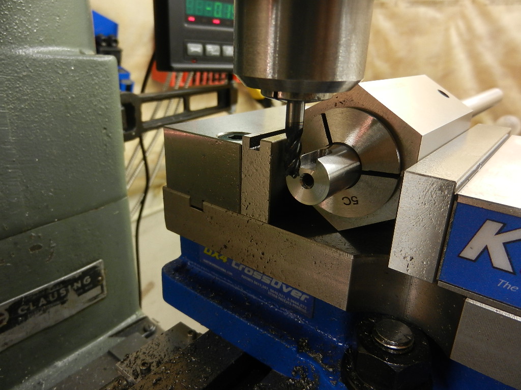
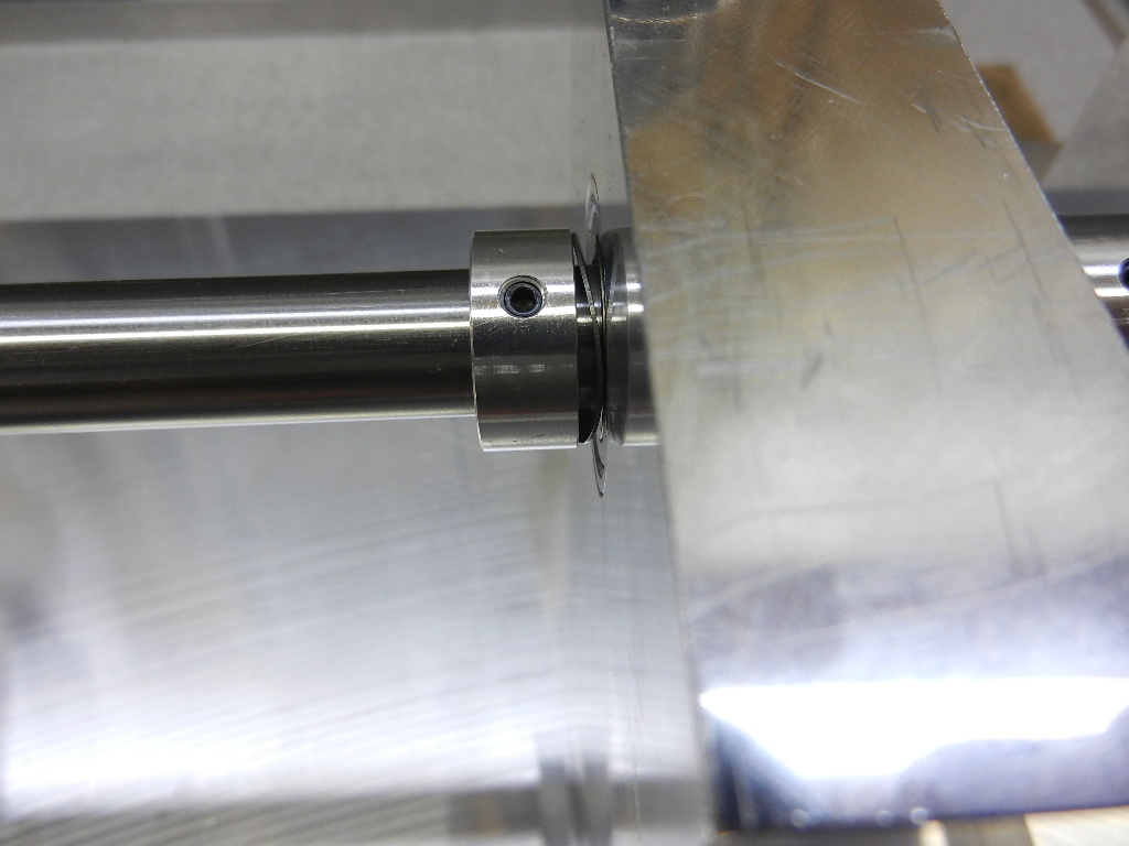
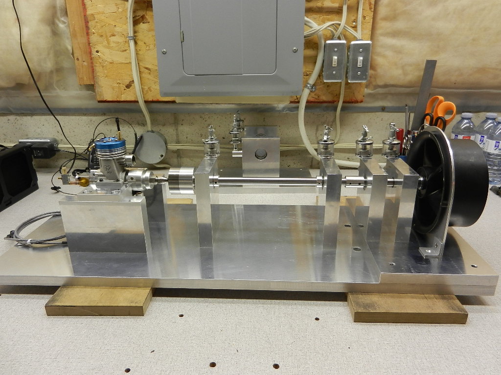
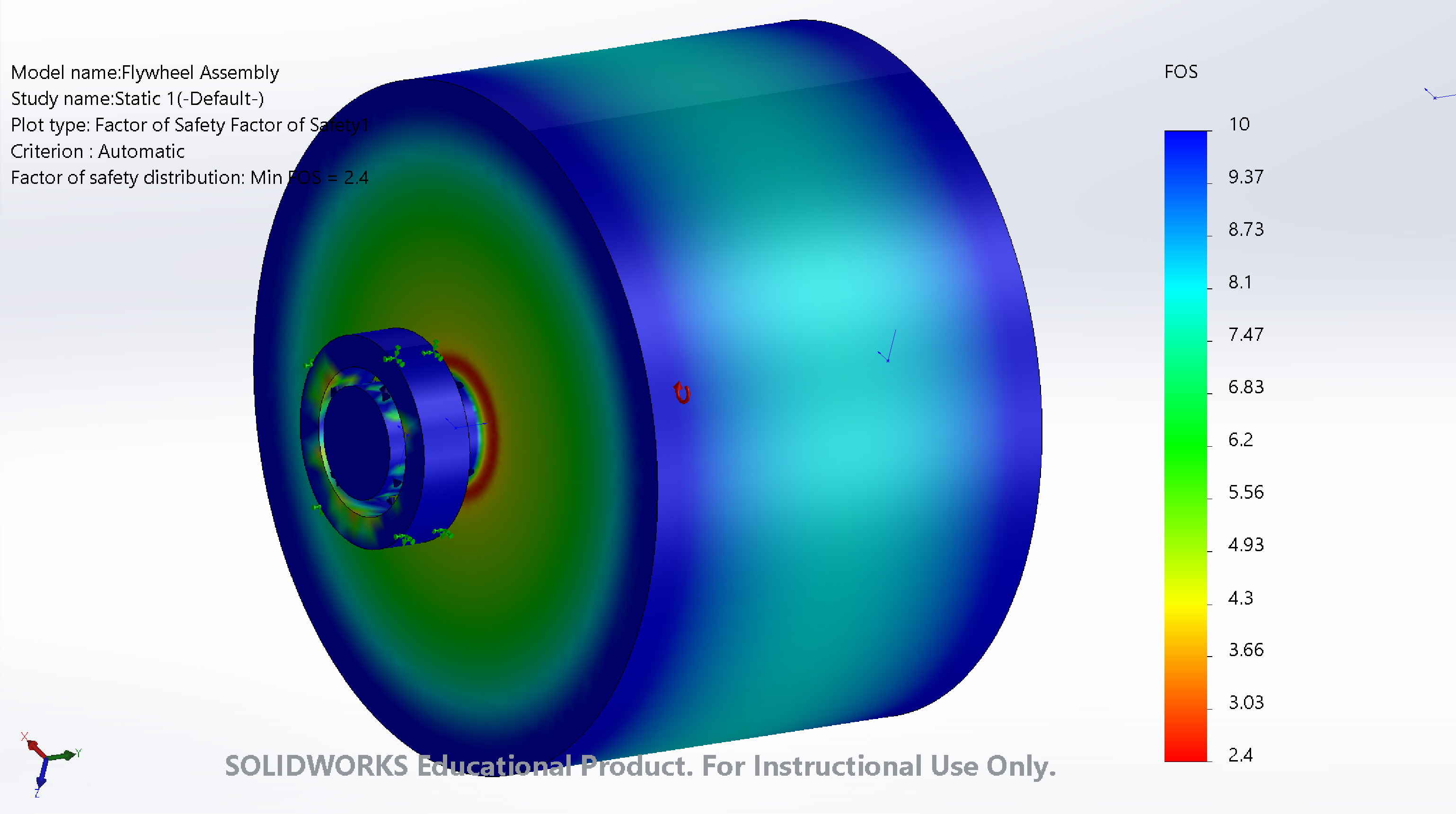
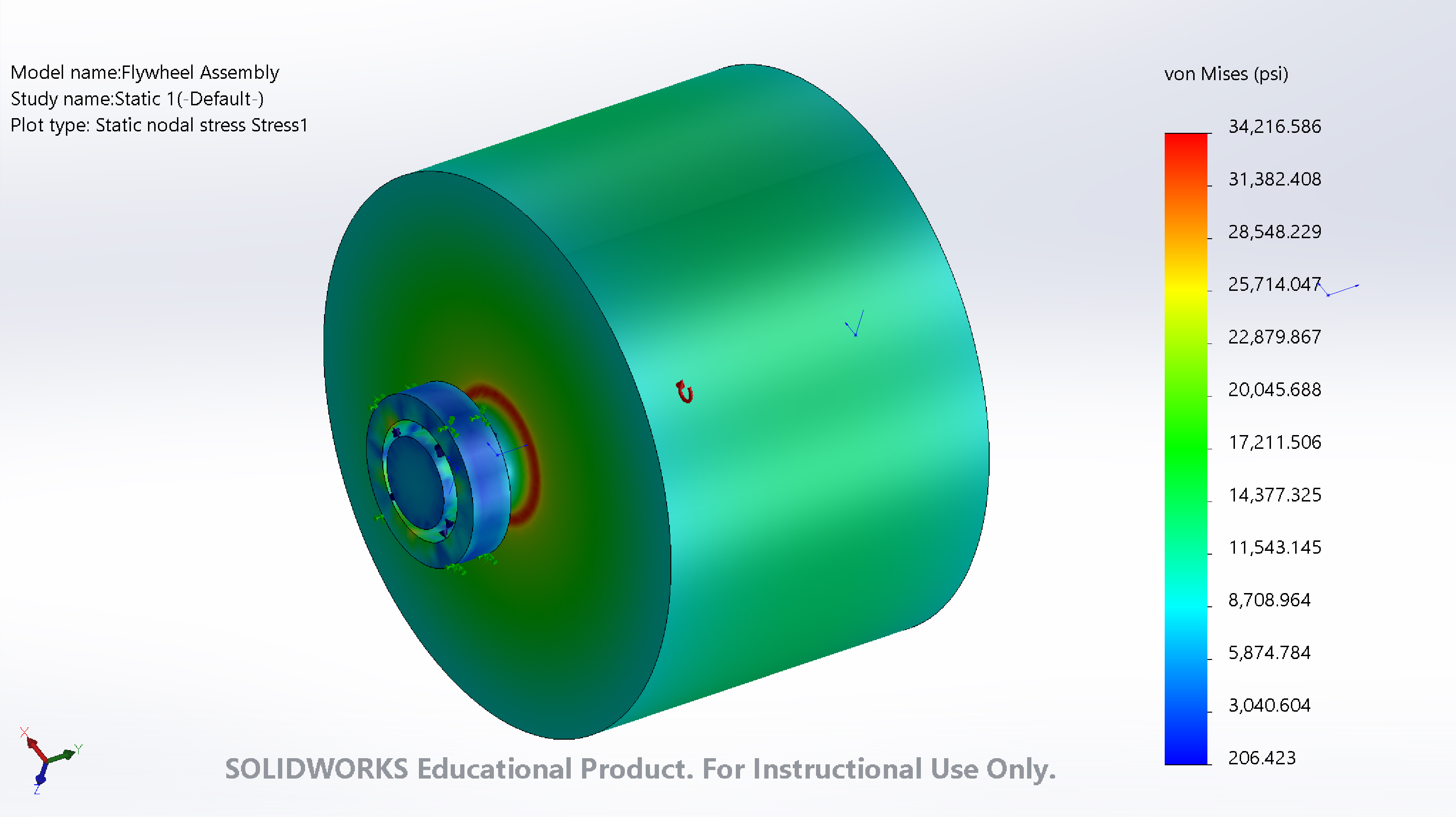
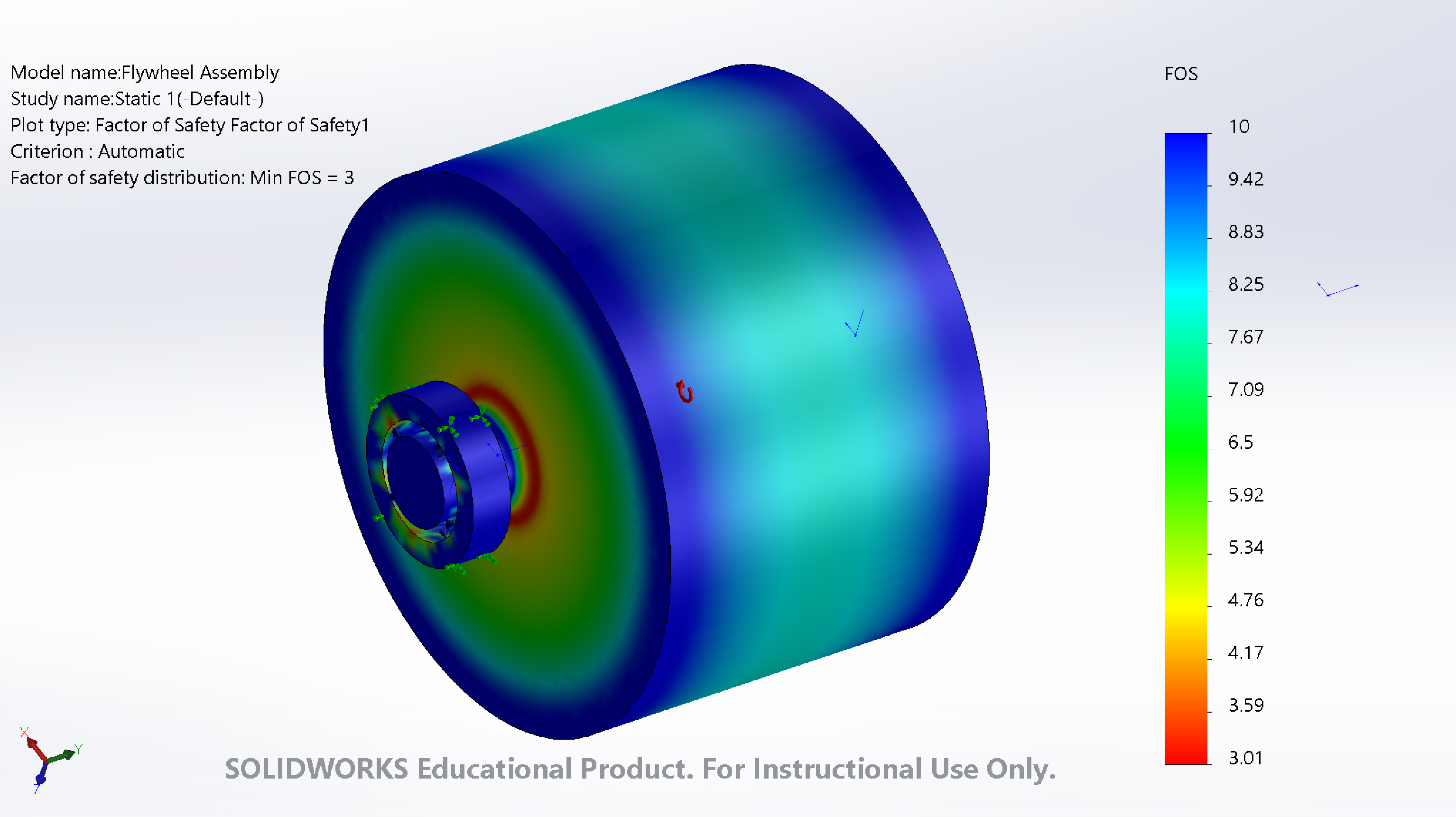
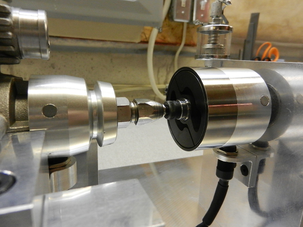
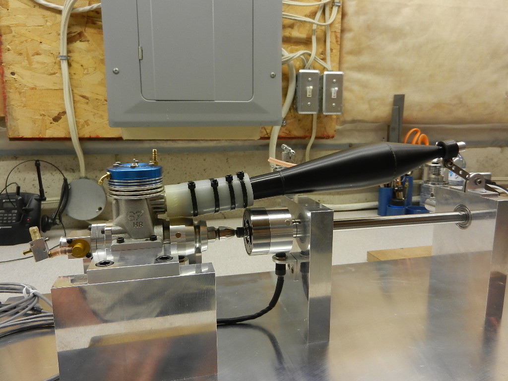
This was intended for testing high speed motors. It has two load sources, one is a big Lehner 30 series motor that is housed in a water cooled reaction torque cradle. The other load source is a turbocharger compressor wheel. A coupler connected the test motor to the dyno motor and could be removed if we wanted to only test with aero load. If we only wanted dyno motor load we removed the compressor wheel and replaced it with a dummy wheel that had the correct inertia and mass, but no blades. When you get into high speed machinery rotordynamics become critical so you have to be mindful of masses and their position on the shaft(s).

We used two motor controllers, one powering the motor under test and the other absorbing the load. The ESC's were connected on the DC bus so only a small power supply was needed to make up for the losses in the loop. The motor and dyno could also be reversed so the dyno motor was powering the motor under test and we could generate motoring/generating maps in both positive and negative torque.

The reaction cradle torque was countered by the load cell and we have a test weight platform to calibrate.
An encoder was used to measure speed and all signals fed into a laptop running Labview.
Cooling water was distributed in the base of the main body to the dyno motor and motor under test. Soft silicone hose ensured the cooling lines imparted minimal reaction torque to the cradle.

This ran up to 45-60kRPM reliably, but beyond that we had issues with the coupler. This was great for working on motor controls and mapping efficiency of the motor at lower speeds. Enough to corrleate simulations and we could extend the simulation to higher speeds. I worked on a higher speed design intended for 180kRPM, but never got around to building it.

IMG_6864.JPGIMG_6929.JPGIMG_6935.JPGIMG_6937.JPGPartially assemled.jpgPre Assembly.jpg
 
Very cool project Tyler!

Amazing what can be done in industry where you have access to better machining capabilities and a decent budget. And some sharp minds to drive it all.

Do you remember what bearings were used to run to 60K? Ceramic/hybrid? Class ratings? How were they lubricated?

What happened to the couplers past 60K?
 
Terry for the LMT motor we are just using the standard ABEC 5 SMF1910-ZZC PS2 bearings. So long as the rotor was balanced properly the bearings had no issues and just a little oil every 10 hours of running. The test motor used a little more exotic angular contact ceramic hybrid ABEC 7 608 size bearings. These need 5-10N of preload which was accomplished with wave springs. These were sealed with a special lube from the supplier. They run up to 180kRPM. The lube provided enough friction that we had to monitor bearing temps with small RTD's.

The Roba DS coupler from Mayr was not supported in the middle piece so it started to vibrate uncontrollably.
The solution to very high running was to adopt a precision steel steel wire drive borrowed from SAW boat experience.
Always nice when you hobby and job can complement each other.
 
"Very cool idea, I remember you sent me some pix of that a while back.

Is that some sort of strain gauge to measure the torque? "

I used a load cell. The plan was to connect it to an Eagle Tree with their analog to digital board. It was also to be used to record rpm. I just got to checking that the brake actually worked.

Lohring Miller
 
My buddy's daughter is in the final year for mechanical engineering and ran the numbers for my wheel.

The numbers for radial and tangential (hoop) stress came out very close to that formula I used earlier.

She also did a Solidworks mock-up that included a "von Mises" yield analysis: von Mises yield criterion - Wikipedia That showed the highest stress (and lowest FOS or "factor of safety") was right at the radius for the stub shaft. The area decreases a bunch by increasing the radius, think I'll go with the 1/4", lol.

Looks like my wheel will hold up as long as there isn't any harmonics or balancing issues...


full


full


1/32" radius at shaft:


full


full


1/16" radius at shaft:


full


full


1/4" radius at shaft:


full


full
 
Last edited:
Have her run the time to accelerate between the start and end rpm. My simplistic assumptions assumed constant torque over the rpm range with an engine BMEP of 100 psi. That gives times that are a little shorter than the actual case. That BMEP is also probably a little high for many model engines. I would be glad to send my spreadsheet.

Lohring Miller


Thanks, I got the spreadsheet from you a while ago, lol.

The online calculators I posted earlier plus the calculations in the Performance Trends s/w all indicate a 30-45 sec. run time which is in the 3-500 rpm/sec. ball park...
 

Latest posts

Back
Top