- Joined
- Apr 27, 2007
- Messages
- 3,369


Sure do miss the days when we made noise with this. I would hate to hazard a guess on how many pulls we made. Must be in the thousands
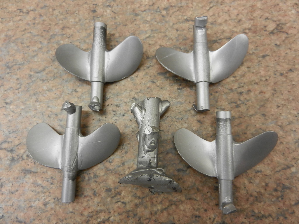
The nitro engine mount is in the lower center. The picture shows the over kill we used to connect the engine. We used a soft square key into Aeromarine square collets followed by a Lovejoy coupling and finally the clutch. The issues we had with this setup were:
1. Failure of the soft element in the Lovejoy coupling. Solved with the hardest available element. There were no issues after that.
2. Wear of the Aeromarine collets. We replaced the elements frequently. They still lasted for hundreds of runs.
3. Failure of the stock clutch arm. Mike made a billet version that has lasted since.
4. Twisting of the key. That occurred slowly over time but was severe when an engine seized. Replacing the key was cheap and easy.
At this point I think the Lovejoy coupling is superfluous and a one way clutch might be a good idea but is not essential. All the other parts of the drive train performed well. Mike replaced the grease lubricated bearings once after years of testing. I think we have experience with more dyno runs than most other hobbyists. I hope our experience can lead others to explore engine tuning with this great tool.
Lohring Miller
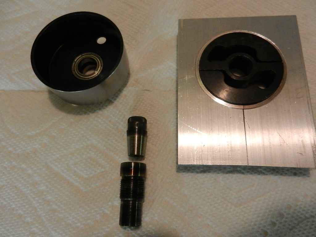
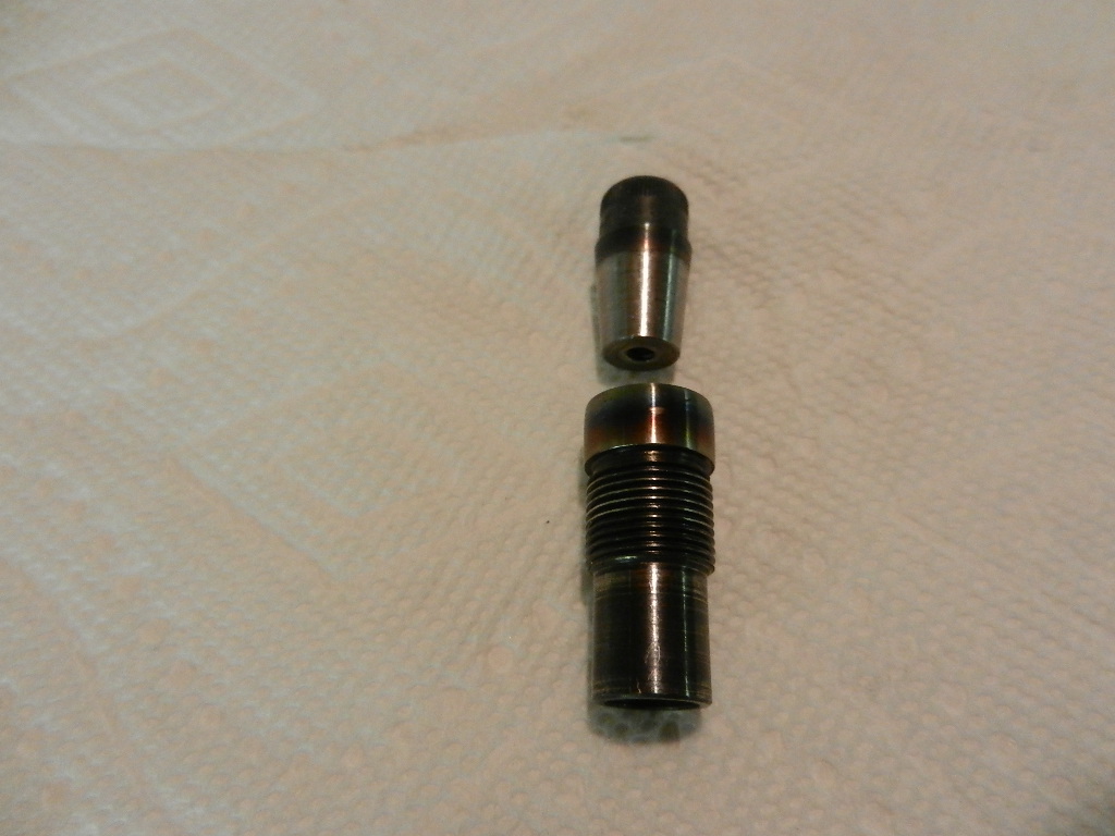


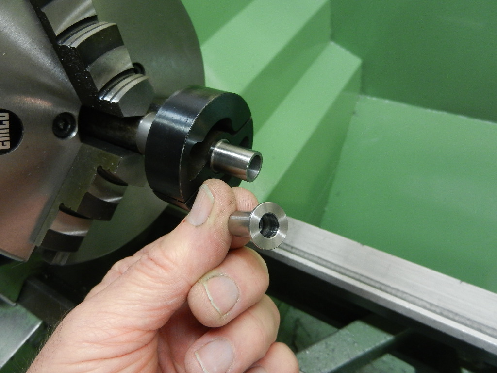
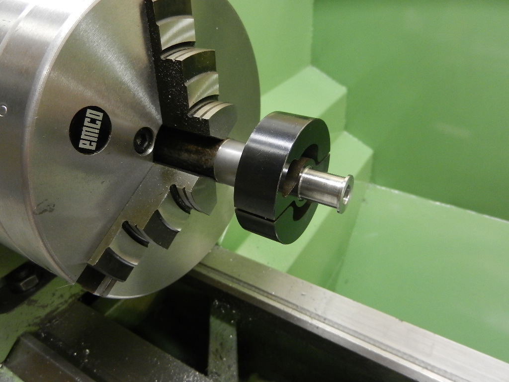
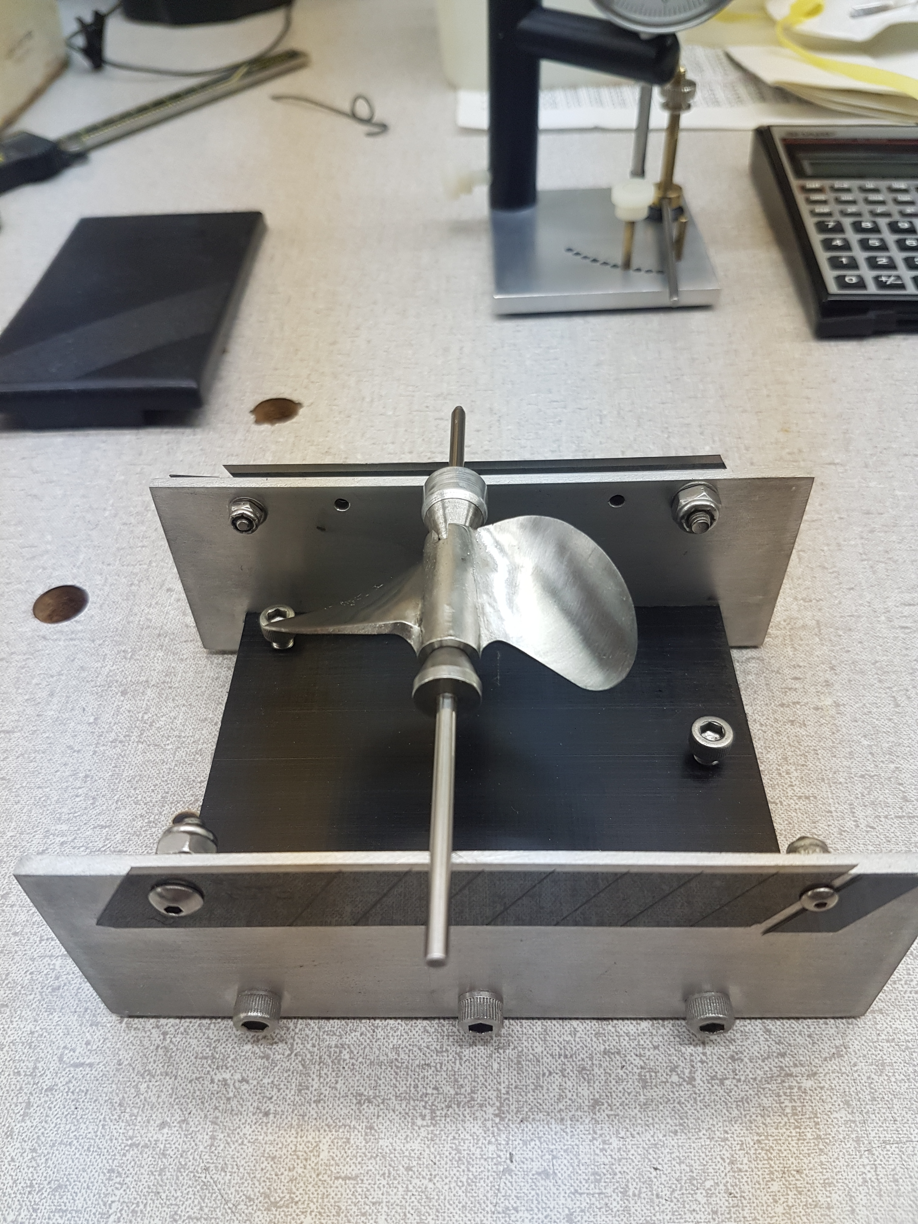
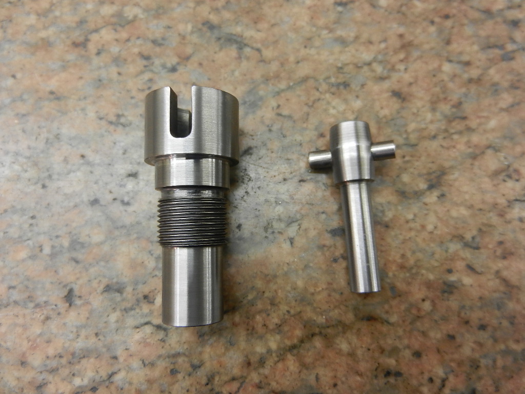
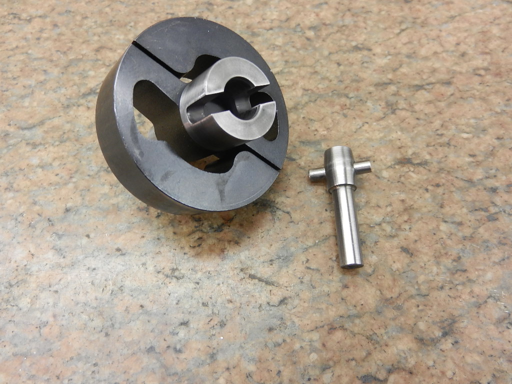
Terry, that CMB universal joint is tightly piloted between the barrel section on the male end and the female engine side.
The coupler only has a few degrees of angular displacement. I believe it was intended to essentially be a straight coupler and only allow torque transfer with no thrust transfer. I'd be happy to send it to you for inspection if you want to scale it down.
Terry,
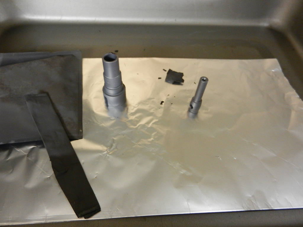
I was wondering if some of these components weren't going to just be throwaway items. Sounds like they are.
Thanks. Brad.
Titan Racing Components
BlackJack Hydros
Model Machine and Precision LLC
We always checked dynoed engines in real boats. Mike held the SAW record for fastest gas boat from 2004 until 2019. His wimpy 97 mph GX1 gas sport hydro record still stands. I say wimpy because the boat was capable of over 100 mph. In fact it blew off on the backup pass at over 100 mph when conditions were so rough no one else was running. We concentrated on the rigger the rest of the weekend. Mike also dominated the unlimited hydro class in District 8 with his rigger.
All this was from a serious test program that started with only an onboard tach and radar gun and ended with Eagle Tree loggers and the dyno. We spent many weekends in my and Mike's shop and at the pond trying sometimes crazy things.
Lohring Miller
View attachment 280444View attachment 280445View attachment 280446View attachment 280447
Terry,
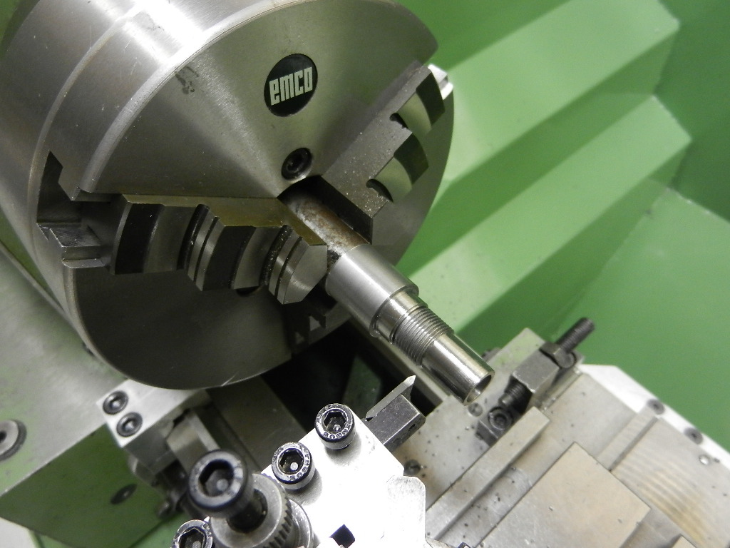
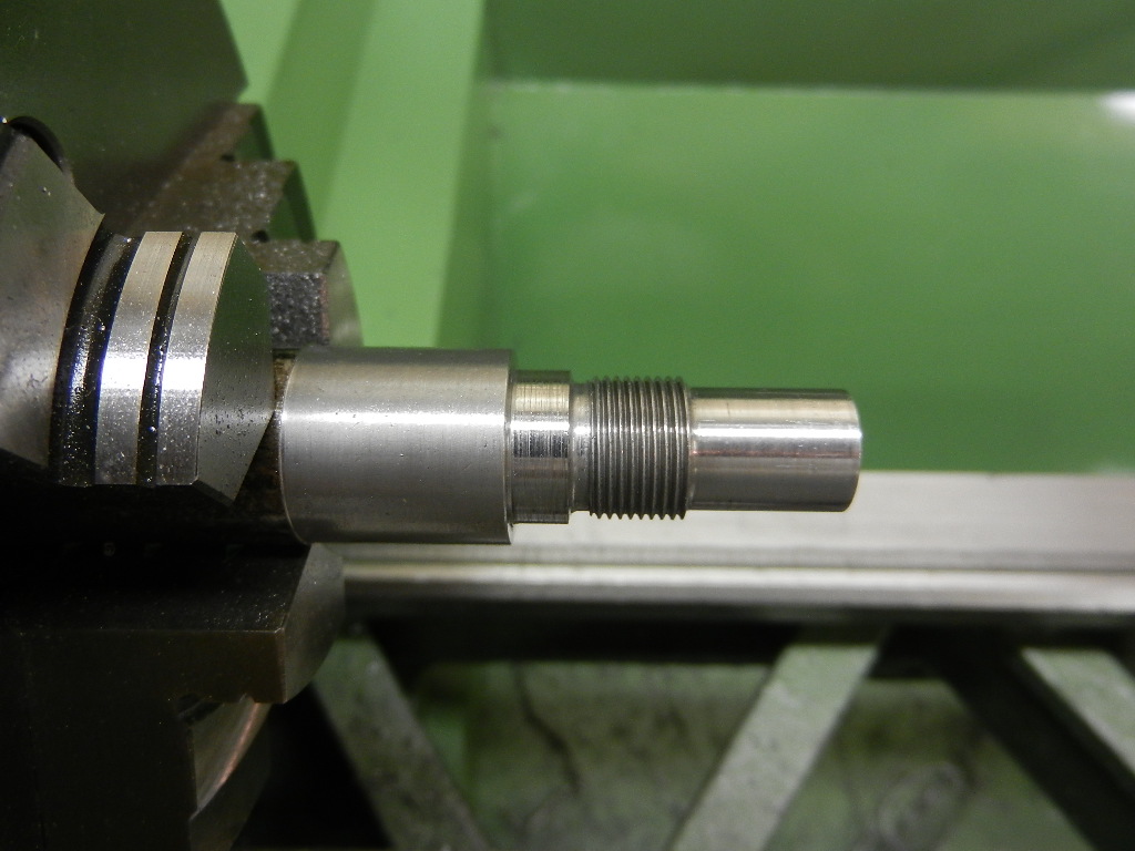
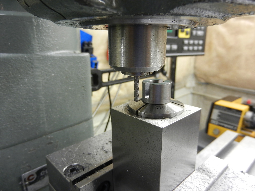
Regarding sizing the hole for the pin, you can use a carbide reamer on 50c S-7 without any problems. The other approach would be midget laps with lapping compound. Leave the hole a little undersize.
Bob

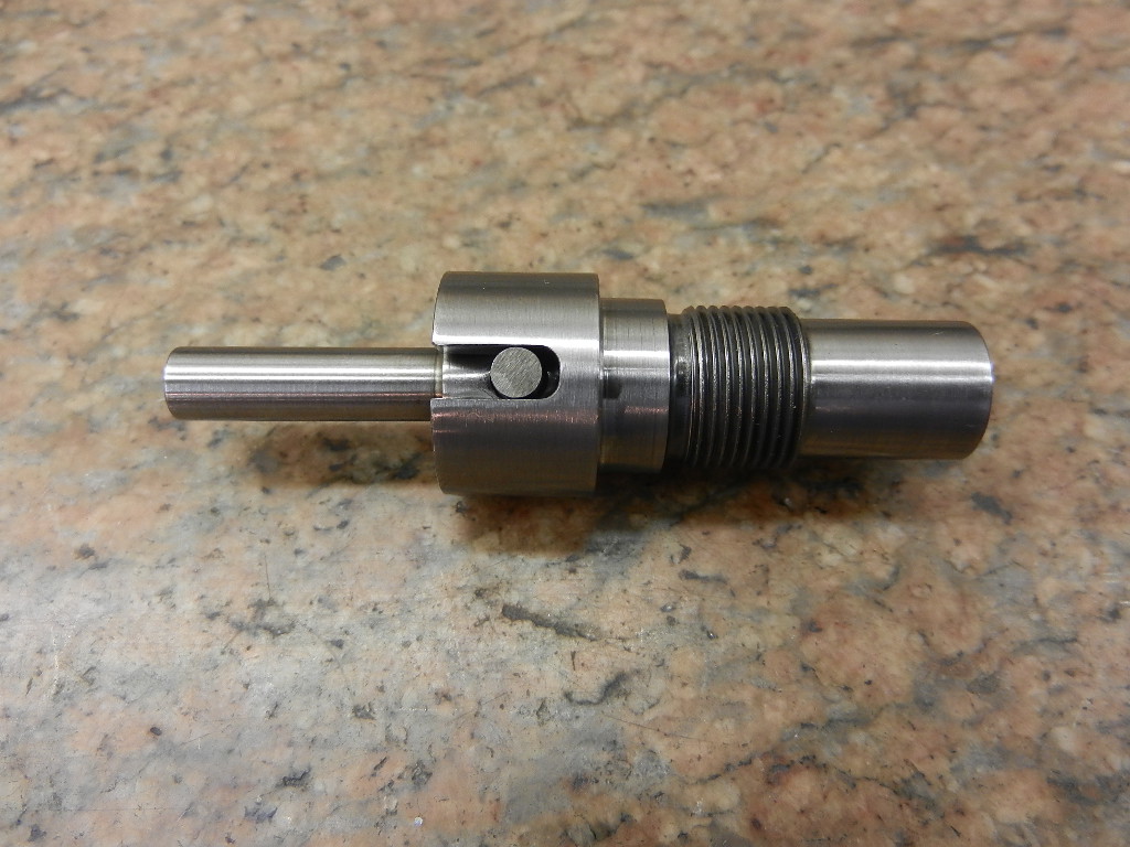
Tyler,Very nice Terry, I think you may see some high contact wear on the pin as you have a small contact area between the pin and flat on the female side coupler. You'll notice the CMB coupler's pin is flat on both ends to reduce the Hertzian contact stress and hence reduce wear. Your pin may just wear in to produce a flat after some running.
Enter your email address to join:


