Run in stand/dyno build.

Intlwaters

Help Support Intlwaters:

This site may earn a commission from merchant affiliate links, including eBay, Amazon, and others.
"I had a prop come apart at the hub testing an OPS 67 years ago, made about a 1" gash in the pavement below, I'll never forget that." This is exactly why I changed to using cut down solid carbon fiber propellers as a loading device. They are expensive ($50.00+) each, however, they can easily withstand RPM's in the 40,000 range. You can never be to safe with one of these test stands.
 

Attachments

  • 008_2013-07-30.jpg
    008_2013-07-30.jpg
    70.8 KB · Views: 70
  • 004_2013-10-30.jpg
    004_2013-10-30.jpg
    65.8 KB · Views: 70
"I had a prop come apart at the hub testing an OPS 67 years ago, made about a 1" gash in the pavement below, I'll never forget that." This is exactly why I changed to using cut down solid carbon fiber propellers as a loading device. They are expensive ($50.00+) each, however, they can easily withstand RPM's in the 40,000 range. You can never be to safe with one of these test stands.


Nice stand.

That prop was sized for the 67, maybe 8" diameter? After that I bought the biggest fiber filled prop I could find (15"?) and cut it down to get the rpm I wanted, no more problems.
 
If you send me the dimensions of your flywheel including the shaft diameter, I can stress check it. I've not heard of any flywheel failures in model engine dynos. Mike, on the other hand, had a propeller failure on a Zenoah that wrecked the engine. We used dyno runs for carb setting and break in as well as testing. I think the short, full power runs worked well for break in. You can see the resuly in the power graphs.

Lohring Miller87 Octane Tests.JPG
 
Hey Lohring. You guys did a lot of pioneering in this area, thanks again for sharing.

I plan to use "HTSR"4340 from these guys, they claim 150 ksi: Steel Grade AISI 4340 | Richmond Steel Canada I'll ask for certs if it doesn't cost too much.

After quite a bit of digging I figured I'd go bigger than probably necessary, being easier to just cut the diameter of the wheel down than completely redesign the whole unit. I checked a few web sites and Machinery's handbook for flywheel safety and think I'm OK but would be happy for you to check. What formulas are you using? They all say not to use a hole and separate shaft as it causes a stress point so I'm going to turn integral shafts into it.

Think I'll go 6" in diameter by 4.5" wide to start with 1.5" long x 25 mm stub shafts on each end. (6005 bearings). I read a lot of places you want the wheel to spin up in 10-15 seconds but Dyno trends states 3-500 rpm/sec is more accurate so that means more like 30-50 sec for a .90 nitro motor. http://performancetrends.com/faq.htm#Inertia_Dyno_Accurate

Plus I'm hoping the longer wind up time will smooth the data and give better results.
 
Last edited:
Terry, those dimensions of 4340 will come in at slightly north of 36 lbs. That seems excessive for nitro motors.
 
Hey Lohring. You guys did a lot of pioneering in this area, thanks again for sharing.

I plan to use "HTSR"4340 from these guys, they claim 150 ksi: Steel Grade AISI 4340 | Richmond Steel Canada I'll ask for certs if it doesn't cost too much.

After quite a bit of digging I figured I'd go bigger than probably necessary, being easier to just cut the diameter of the wheel down than completely redesign the whole unit. I checked a few web sites and Machinery's handbook for flywheel safety and think I'm OK but would be happy for you to check. What formulas are you using? They all say not to use a hole and separate shaft as it causes a stress point so I'm going to turn integral shafts into it.

Think I'll go 6" in diameter by 4.5" wide to start with 1.5" long x 25 mm stub shafts on each end. (6005 bearings). I read a lot of places you want the wheel to spin up in 10-15 seconds but Dyno trends states 3-500 rpm/sec is more accurate so that means more like 30-50 sec for a .90 nitro motor. http://performancetrends.com/faq.htm#Inertia_Dyno_Accurate

Plus I'm hoping the longer wind up time will smooth the data and give better results.

Terry,
I hope you plan on balancing this flywheel to an ISO G2.5 or better level. Even the best material will have slight density differences leading to imbalance. The small imbalance forces yield very high radial loads which destroy the bearings in short order. I can recommend a shop for you if you have no local resources.

-Tyler
 
Terry, Tyler,

Yup. It's definitely worth the investment.

There's a company here in the Greater Dayton area called BalCo (imagine that :rolleyes: ) that does dynamic up to something like 80K.

Thanks. Brad.
Titan Racing Components
BlackJack Hydros
Model Machine and Precision LLC
 
Yup, thanks guys. I was just gonna static balance it but my buddy Rudy also recommended dynamic balancing. A quick look came up with many shops that do electric motors etc.

I'll have to read up on ISO G2.5, thanks!

30+ lbs. at 30K, would be pretty exciting to have a failure there...
 
Last edited:
Small world Brad, I have worked with BalCo quite a bit and would recommend them.

Terry, Tyler,

Yup. It's definitely worth the investment.

There's a company here in the Greater Dayton area called BalCo (imagine that :rolleyes: ) that does dynamic up to something like 80K.

Thanks. Brad.
Titan Racing Components
BlackJack Hydros
Model Machine and Precision LLC
 
That's way too big for an 11 cc engine. If you bore through the center for a 25 mm shaft the stress at the bore will be around 54,000 psi at 30,000 rpm. The center stress for a solid flywheel will be similar. I recommend a ground shaft secured with Locktite to avoid the added stress from a press fit. The same calculation on our 5.18 " OD by 3.33" long flywheel with a 5/8" shaft shows 28,000 psi at 25,000 rpm. In addition an estimate of the run up time from 12,000 rpm to 30,000 rpm for your flywheel would be around 75 seconds. The same calculation from 12,000 rpm to 25,000 rpm for our flywheel is around 10 seconds.

My thoughts for an 11 cc flywheel is 4.5" diameter by 2" long with a 17 mm shaft. That gives a bore stress of a little over 30,000 psi at 30,000 rpm with a run up time of around 10 seconds. That will save you money and will be a lot safer. My latest design plans on using 1045 disks. See McMaster-Carr You can have them heat treated and then grind the OD and ID if you want to be really safe. See Hardness Conversion Table: Brinnel/Rockwell Tensile Strength for the relationship. Our flywheel came heat treated to 35 Rockwell C. It was still machinable. As Tyler said, you need to have everything balanced. We did.

Lohring Miller

PS These are the TDK calculations to help estimate flywheel size. I used my own and only the stress calculations were checked by a real engineer.

If you really need to know more than the guidelines given above, here are the relevant formulas...

The formula for determining the torque is:

Torque = PM * rpm per second / 9.551

where "PM" represents the Polar Moment of Inertia of our inertia dyno's flywheel.

If you don't know the Polar moment of Inertia for the flywheel (and your flywheel has a constant thickness cross-section) we can calculate it with the formula:

PM = (W * r^2) / 32.16 / 2

where "W" represents the flywheel weight in pounds and r is its radius in feet.
(the formula for weight of a steel disk can be found in the "FAQ" page)

Once you have the torque, it is easy to calculate the horsepower with the standard formula:

Hp = Torque * rpm / 5252

Keep in mind that the rpm in the last formula must be the average rpm during the sampling period.

Say our example uses a 10 pound flywheel, 8" in diameter (thus it would have a Polar Moment of Inertia of .017 foot-pounds-second^2). If the engine was able to accelerate this flywheel from say 4,800 rpm to 5,200 rpm in 2/10 of a second (a rate of 2,000 rpm per second) that would represent a torque of 3.6 pound feet. Since our above example had an average rpm of 5,000, it produced 3.4 Hp during the test.
 
Last edited:
One for Ray, lol!


full
 
Hi,
Jim Gale has the teststand you need as it let you optimice not only the engine , he has always the complete drive so also the propshaft and the propeller are attached. As all run with water the motor cooling is no problem. Note that the water is running in a closed circle and he messured rpm and trust at different speed.

Happy Amps Christian
 

Attachments

  • 08C926FA-A085-409C-8A34-AF34F725A87E.jpeg
    08C926FA-A085-409C-8A34-AF34F725A87E.jpeg
    1.2 MB · Views: 76
  • DA803306-3B44-4911-92CE-E096FC8B7066.jpeg
    DA803306-3B44-4911-92CE-E096FC8B7066.jpeg
    878.3 KB · Views: 74
That's way too big for an 11 cc engine. If you bore through the center for a 25 mm shaft the stress at the bore will be around 54,000 psi at 30,000 rpm. The center stress for a solid flywheel will be similar. I recommend a ground shaft secured with Locktite to avoid the added stress from a press fit. The same calculation on our flywheel 5.18 " OD by 3.33" long flywheel with a 5/8" shaft shows 28,000 psi at 25,000 rpm. In addition an estimate of the run up time from 12,000 rpm to 30,000 rpm for your flywheel would be around 75 seconds. The same calculation from 12,000 rpm to 25,000 rpm for our flywheel is around 10 seconds.

My thoughts for an 11 cc flywheel is 4.5" diameter by 2" long with a 17 mm shaft. That gives a bore stress of a little over 30,000 psi at 30,000 rpm with a run up time of around 10 seconds. That will save you money and will be a lot safer. My latest design plans on using 1045 disks. See McMaster-Carr You can have them heat treated and then grind the OD and ID if you want to be really safe. See Hardness Conversion Table: Brinnel/Rockwell Tensile Strength for the relationship. Our flywheel came heat treated to 35 Rockwell C. It was still machinable. As Tyler said, you need to have everything balanced. We did.

Lohring Miller

Interesting.

Everything I've read says not to drill a hole in it as it causes a stress point, maybe that's why you're coming up with such a high stress figure? What formulas are you using for stress calculations?

I posted this on a machinist's forum and someone linked a formula: Solid Disk Flywheel Design | Engineers Edge | www.engineersedge.com

solid-flywheel-10.png


For a wheel at 152.4 mm in diameter & 30,000 rpm:

p = 7800

u = 0.3

v = peripheral velocity in m/s.

I get a peripheral velocity of 239.4 m/s and stress of 184.4 N/mm2 or 26,700 psi, well below the 150,000 psi tensile strength for 4340 but only a safety factor of 5.6.


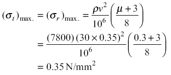
I also found a section in the Machinery's Handbook titled: "Centrifugal Stresses in Flywheel Rims":

In general, high speed is desirable for flywheels
in order to avoid using wheels that are unnecessarily large and heavy. The centrifugal
tension or hoop tension stress, that tends to rupture a flywheel rim of given area,
depends solely upon the rim velocity and is independent of the rim radius. The bursting
velocity of a flywheel, based on hoop stress alone (not considering bending stresses), is
related to the tensile stress in the flywheel rim by the following formula which is based on
the centrifugal force formula from mechanics.

V = square root (10 × s) or s = V squared ÷ 10

where V = velocity of outside circumference of rim in feet per second, and s is the tensile strength of the rim material in pounds per square inch.

This for a one piece wheel which is what I'm using.

My surface speed at 30K will be 785.4 ft/sec so the minimum tensile strength with a factor of 10 works out to 61.7 ksi.


Ya, I know I'm thinking bigger on the wheel than what's been done in the past. Most information you come across states you want a run up time around 10 -15 seconds, but they don't say what rpm range that is for. A car engine would probably run between 1-8,000 rpm so that's about the 500 rpm/sec Performance Trends talks about. For a nitro motor it's more like 15-30K so a run time of 30-50 sec. is more like it. Also, I'm hoping to get smoother curves and more accurate data, I've heard lots of issues with data spikes from you and others. Don't know if it'll work, the 1/4" flex cable "fuse" might twist in two the first time I open the throttle!

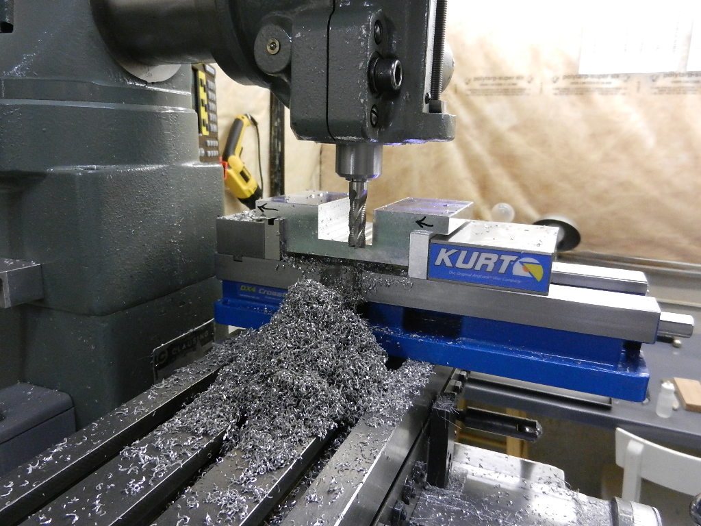
I'll finish turn the wheel between dead centers (thanks Rudy) so it'll be accurate but also so that I can easily put it back on the lathe and trim the diameter if needed.
 
Last edited:
Terry,
I hope you plan on balancing this flywheel to an ISO G2.5 or better level. Even the best material will have slight density differences leading to imbalance. The small imbalance forces yield very high radial loads which destroy the bearings in short order. I can recommend a shop for you if you have no local resources.

-Tyler

Doing some initial research, quite a bit of info on dynamic balancing, thanks for the heads up!

http://www.irdbalancing.com/assets/balance_quality_requirements_of_rigid_rotors.pdf
 
Terry, it is true that the highest stress for a flywheel with a hole in the middle is the bore. I know this very well from compressor wheel and turbine wheel designs in turbochargers. In an ideal world you would machine your flywheel with stub shafts integral, but that's not the easiest solution. You want to avoid additional stress risers on that bore like a high interference fit between the shaft and flywheel. A light interference fit would ideal to have the best compromise of stress versus possible balance migration.
 
Back
Top