Run in stand/dyno build.

Intlwaters

Help Support Intlwaters:

This site may earn a commission from merchant affiliate links, including eBay, Amazon, and others.
Here's another "dirty" picture just for Ray, lol!


full
 
Last edited:
Terry, it is true that the highest stress for a flywheel with a hole in the middle is the bore. I know this very well from compressor wheel and turbine wheel designs in turbochargers. In an ideal world you would machine your flywheel with stub shafts integral, but that's not the easiest solution. You want to avoid additional stress risers on that bore like a high interference fit between the shaft and flywheel. A light interference fit would ideal to have the best compromise of stress versus possible balance migration.
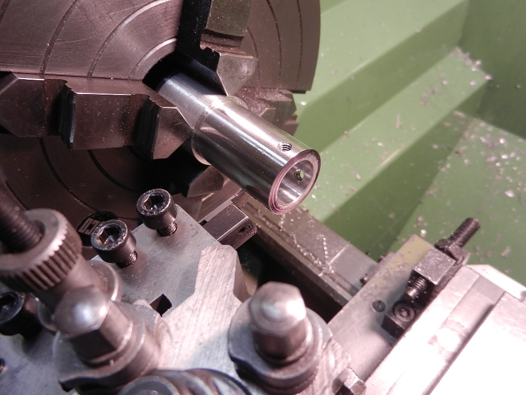
IIRC it is. I can't remember exactly where I read it but apparently it's not the way to go to minimize stress in the wheel. Maybe that's why Lohring's numbers are higher?

With an integral shaft the maximum stress is at the rim where the max speed is, that's what the formulas I mentioned are for. Any of your engineering buddies care to run the numbers for me?

I plan to rough turn it with a 4 jaw and finish it between dead centers, my "consigliere" says that's the most accurate way to go plus the best way to be able to trim it and maintain accuracy later if needed.

Maybe one of our toolmakers here will chime in on that?
 
Last edited:
"I plan to rough turn it with a 4 jaw and finish it between dead centers, my "consigliere" says that's the most accurate way to go plus the best way to be able to trim it and maintain accuracy later if needed"

If the centers were "LAPPED" into "hardened material", this would certainly be doable. It is the same technique which is used on any OD, ID grinder when making the same diameters on different shafts of the same length. Accuracy can be held to + or - .00005", providing the centers are "LAPPED"!

Any machining between lathe centers should only be done after the centers have been checked for alignment. The four jaw chuck should also be checked for alignment to the lathes center line not only at the chuck, but at some distance from the chuck.

Maybe one of the problems when discussing things such as a "light press fit" or a "slip fit", no dimensions have been given for the shaft size compared to the hole size. If the shaft size was 1.000", + or - .00005", what should the hole size be for a "slip fit"? What should be the hole size for a light "press fit"? Should the hole be machined or ground? Lots of things to consider here.

Jim Allen

Note: I had a very well known M.E. ( Henry Nelson) check Lohrings numbers. They are correct & this could be one of the reasons that the inertia dyno he used functioned without any problems!


Thanks Jim, I'll check into lapping the centers.

I think my 4 jaw is pretty good, I took a skim cut off the plate before mounting the chuck and then took another skim off the OD. The jaws are out slightly tho as this showed up when I reground the spindle for my mill, I had to jank around to get the far end running true with the end near the chuck. But as mentioned I'll only be using it to do the roughing, I'll final turn it between the centers.

Just to be clear, I'm not questioning Lohring's figures whatsoever! I'm just trying to find out why they're higher than what I've come up with. I think it might be because he used a separate shaft.

Again, I'm going to turn the stub shafts on each end right into the wheel so it's all one piece.
 
Last edited:
Thanks Jim, I'll check into lapping the centers.

I think my 4 jaw is pretty good, I took a skim cut off the plate before mounting the chuck and then took another skim off the OD. The jaws are out slightly tho as this showed up when reground the spindle for my mill, I had to jank around to get the far end running true with the end near the chuck. But as mentioned I'll only be using it to do the roughing, I'll final turn it between the centers.

Just to be clear, I'm not questioning Lohring's figures whatsoever! I'm just trying to find out why they're higher than what I've come up with. I think it might be because he used a separate shaft.

Again, I'm going to turn the stub shafts on each end right into the wheel so it's all one piece.

Terry,

You might consider sending the flywheel to a brick-n-mortar grind shop for final grind. I know you are keen to do things yourself, but you may be venturing into territory where the necessity for precision is paramount. I send all my grind work to a local shop that does grinding only, and they are very good at it. Even if turned between centers, turning will still create variances in diameter and concentricity you will never be able to get rid of. Plus, there's nothing like having that perfect slip fit for your bearings.

Don't forget to include at least SOME fillet radii in the transitions from diameters to faces. this is where your cracks will start if there are sharp inside corners.

Thanks. Brad.
Titan Racing Components
BlackJack Hydros
Model Machine and Precision LLC
 
The reason we went with a separate shaft was that it was easier to make everything accurately. We lightly turned the flywheel between centers after the shaft was in place. Many inertial dyno builders made replaceable flywheels so the load could be varied for different engines. One of the first model engine dynos was built this way. I believe it was a Marty Davis/John Ackerman dyno. I still think you will regret such a large size. One of the real advantages of inertial dynos is that the quick runs collect a lot of data with minimal wear on the engine.

Lohring Miller

Marty Davis Dyno.jpg
 
Beautiful work Terry. After everything is assembled & lined up, consider the use of 1/4 " dowel pins as master locators. All the parts on my test stands were fastened with countersunk SHCS & 1/4" dowel pins. Doing this makes assembly after disassembly a piece of cake!

Jim Allen
 

Attachments

  • dynamometer%20002.jpg
    dynamometer%20002.jpg
    70.7 KB · Views: 54
  • dynamometer%20007.jpg
    dynamometer%20007.jpg
    63 KB · Views: 55
  • dynamometer%20041.jpg
    dynamometer%20041.jpg
    69.7 KB · Views: 52
Beautiful work Terry. After everything is assembled & lined up, consider the use of 1/4 " dowel pins as master locators. All the parts on my test stands were fastened with countersunk SHCS & 1/4" dowel pins. Doing this makes assembly after disassembly a piece of cake!

Jim Allen
What Jim said. Dowels are your friends.

Yup, all parts are pinned for location. I did it three times, what a PITA!

I first tried to just locate everything off the DRO since after testing it was right on. Figured I'd drill/ream the holes in the base, then each part separately and it should all go together, right? Wrong! Problem was I had to move the plate a few times and was working at the limits of the travels so it wasn't right. I was lucky to discover this before putting holes in the pillow blocks.

Plan B. Line everything up using the shaft for reference (it checked very straight), make some custom drill bushings to transfer the holes to the pillow blocks, drill and ream. It was close but not perfect, the main plate was pretty good but the sub plates were off, I figured the drill wandered a thou or two.

Plan C: Make a couple one and two thou offset (cam) pins and line up the main plate. Good. Re-align the sub plate pillow blocks and re-bore the holes with the plates upside down on the mill using the boring head. Press in bigger pins. Finally! I own my buddy Rudy big time for consulting fees, he saved the whole project fur shur.

I guess I'm probably a little OCD (or stubborn, or just plain stupid) but I want to use solid couplings between the main shaft and the sub plates to both transfer the power better and to keep vibration to a minimum. To do this they must line up perfectly.

Like I said, working to tenths for weeks sucks, I don't know how you guys in the trades do it!
 
Last edited:
Here's something else Terry said in post #4 that you missed telling us about Dennis.
"Thanks for all your help, much appreciated. As you know I've been "harvesting" info for quite a while now from Lorhing Miller, Dave Marles, Ken Retallick, Jim Allen, Mikey Ross, Brian Spitzer and Marty/Brian Callahan. I think I have a good plan. As you say, the Datamite Mini USB is supposed to be good for simple inertia dynos, I went with the hall sensors as I figured out how to get good data with them using the Eagle Tree. I also got the built in weather sensors to compensate for air density. http://performancetrends.com/dtm-hdwe.htm"
 
Hey Terry, in the case that the plastic blades do not hold up Schubeler has very nice balanced carbon reinforced plastic fan assemblies.
They attached via a collet to the 8mm motor shaft and run very true. This one has been run up to 45kRPM.

IMG_8317.JPGIMG_8319.JPGIMG_8320.JPG
This was a test on 6S before running to 10S.

 
Hey Terry, in the case that the plastic blades do not hold up Schubeler has very nice balanced carbon reinforced plastic fan assemblies.
They attached via a collet to the 8mm motor shaft and run very true. This one has been run up to 45kRPM.

View attachment 279914View attachment 279915View attachment 279916
This was a test on 6S before running to 10S.


Cool, thanks!

There weren't a lot of options available for a pusher configuration which I wanted so the air flow (and oil etc.) was blowing away from me.

Then I remembered the old Byron units and found one on FleeBay, I also picked up a couple extra fan units if they need to be cut down to increase rpm. They look like some sort of nylon, hope they hold up!
 
Back
Top