Ricky Neal
Well-Known Member
- Joined
- Dec 5, 2020
- Messages
- 149
Thanks Rody,Hello Ricky, first of all good luck with this venture. We do not know each other but I have some very old connection with the Metkemijer brothers and we all share the same passion.
I have read this post with interest and would like to share with you some of my findings and let you guess the rest...
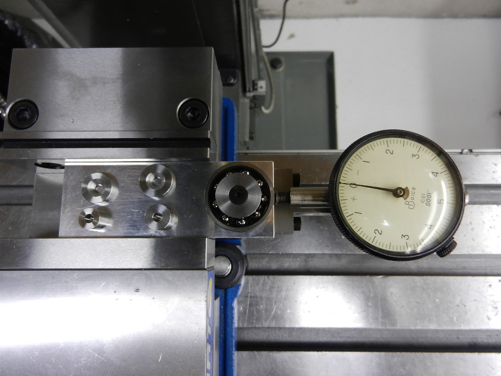
To prevent the bearings from rotating in the crankcase we need to make a press-fit for the bearings. As you probably know there is always a working tolerance for the bearing fit in the crankcase as there is a tolerance for the outside and inside diameter of the bearing itself.
So there will be a situation where the combination of both the fit is very tight or less tight.
This is one of the reasons why we use bearings with more internal play(C3), just to compensate and to have a free bearing once the bearing is in place. A bearing with not enough play will prevent the engine from performing and also fail prematurely.
")
I appreciate your input. I admire what the Metkemijer brothers have done with their engines. they are very clever.
Re - the bearing clearance, I am aware of the bearing fits and clearances but we were confused as to why CMB uses a loose fit for their bearing to the shafts. It seems very common to have inner races spinning on the shaft. See the picture below. I was guessing as to why this may be the case as it seems unique to CMB engines - what do you think may be the reason?