- Joined
- May 28, 2004
- Messages
- 4,235
Safety glasses not going to stop a 40 ton wheel LOL


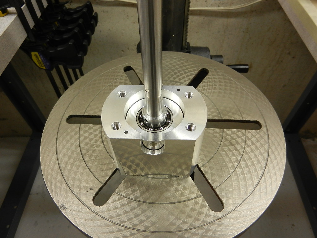
This is what I run most days. The direct drive makes for a straight forward build and at the RPM we are running with the model engines I don't see an easy solution to changing engine/ Inertia ratio but it does mean the wheel needs to be matched to engine output. Unfortunately this means the dyno has a fairly narrow window of application. When Lohring and I were starting to dyno different sized engines we talked about having additional wheels that would live on the shaft and could be attached/ detached a little bit like barbells to increase or decrease inertia.

Dyna Pro Dynamometers Ltd. Had it about 7 years now. Great dyno!

. 8 to 12 years old and looking to Formula one.
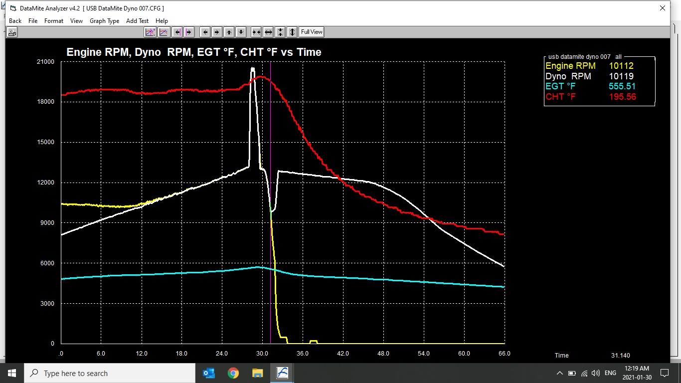
Everything looks good up to about 13500. and you are nowhere near the torque limit on the clutch bearing. Does the clutch bearing have any kind of rpm mechanical limitation? The kart dyno has a one way bearing but the most it ever see's is about 3000rpm. One of the reasons we did not include a one way bearing in the small engine dyno was a concern about how high centrifugal force on the rollers might effect its operation, this coupled with the fairly low torque throughput at certain RPM's and the rotational spikes of the engine, We discussed it and thought it could be troublesome. Having no data on any of this we decide to forgo it and rely on the drive key shearing in the event of a engine malfunction. Just a thought!
I must admit our build was a very close copy of what Midwest engines had built. So we went the safe route. I like the fact you are trying to improve upon this design. I always enjoy the lessons I learn through my failures. Keep up the fight!
Off subject but I think you will appreciate this. Christmas present from my wife, just finished. Hemingway Kits The Dynamic Tool Post Grinder
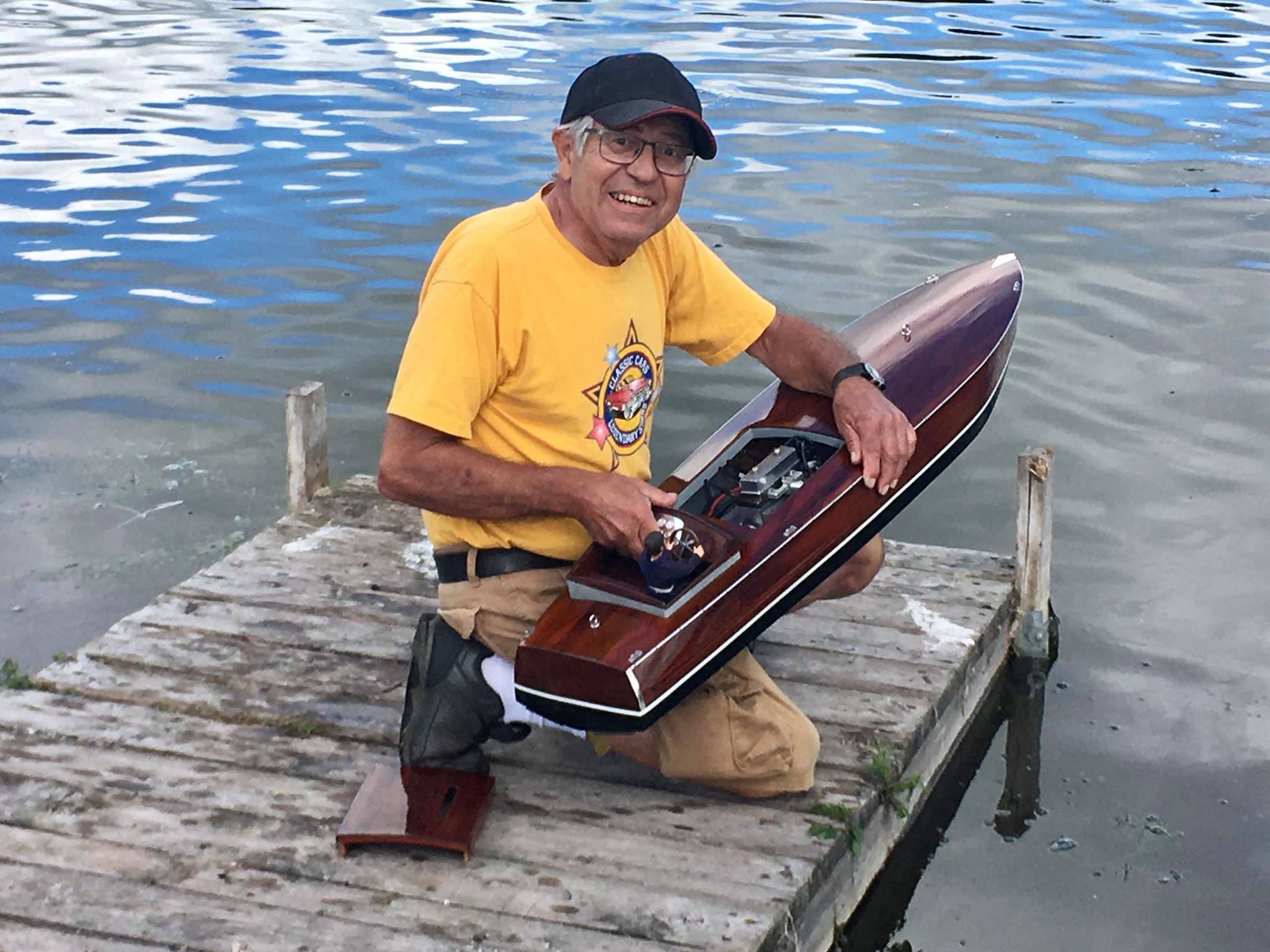
Beautiful job Rudy has done! The engine I am building is similar but simpler in design. .Yup, torque for about 5 hp at 25K is only one ft.-lb (192 oz-in) so nowhere near that limit. Can't find any rpm data for it. Seemed to work OK with the fan to 28K but that's not the load of the wheel of course.
I'll keep at it, got the wheel trimmed to 5.5" diameter which changes the inertia from 1 to about 0.7 lb-ft2. I really like the idea of a one way bearing to release the wheel, not only for a failure but at the end a run too.
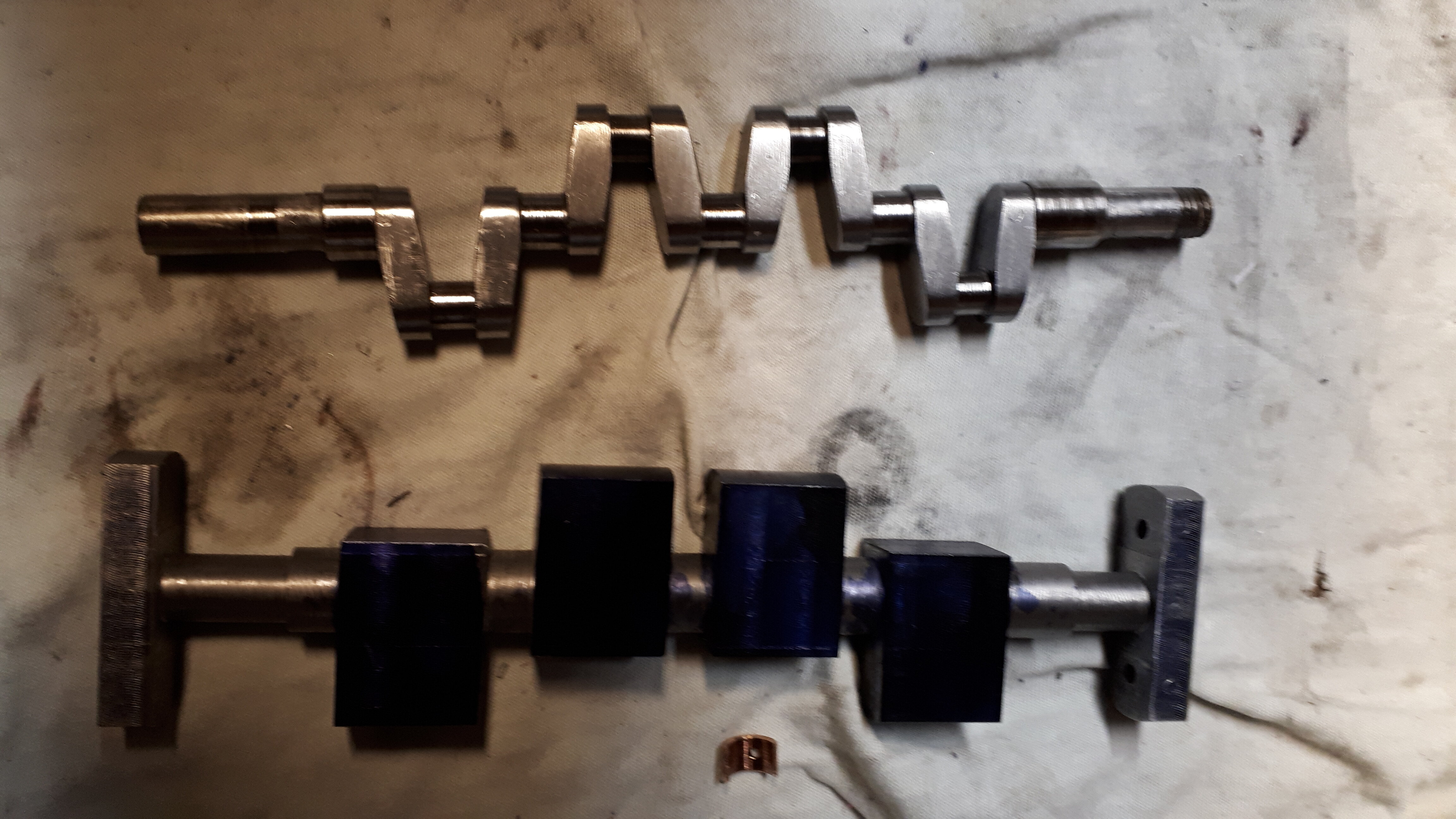
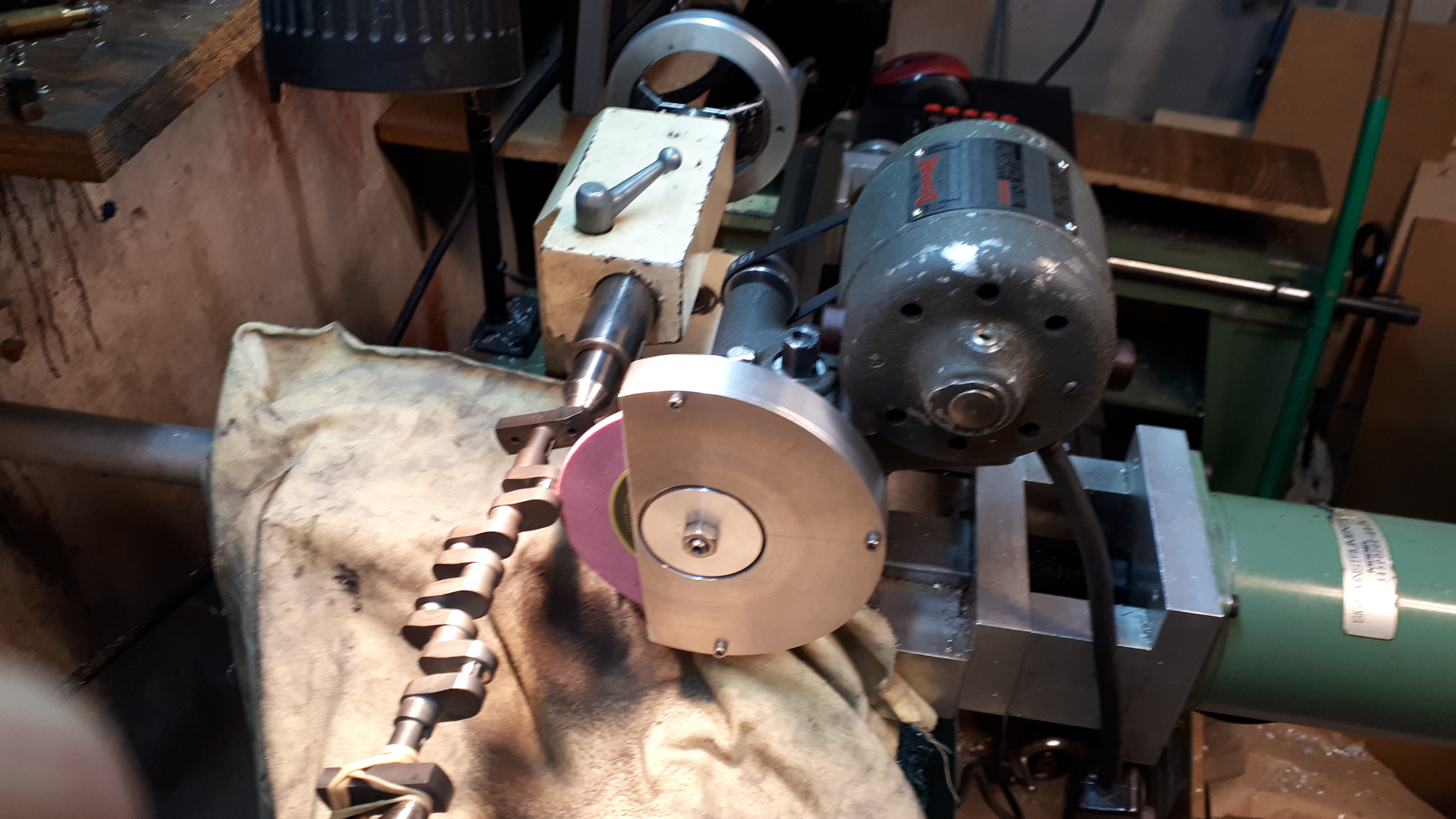
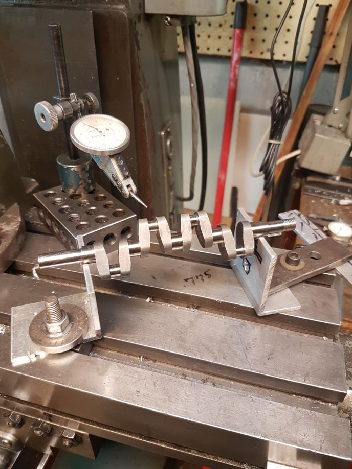
That's a very nice toolpost grinder, they've got some cool stuff on that site. Funny, my buddy Rudy just finished grinding a crank for his inline 4 cylinder, he was running one made of 4140 HT but it wasn't holding up so he made one from heat-treated A-2. Ground it with a little Dumore grinder and a 4" chainsaw wheel.
What's that crank going in? Is that a Myford your grinder is sitting on?
ps: Your wife's a keeper, but you already knew that!
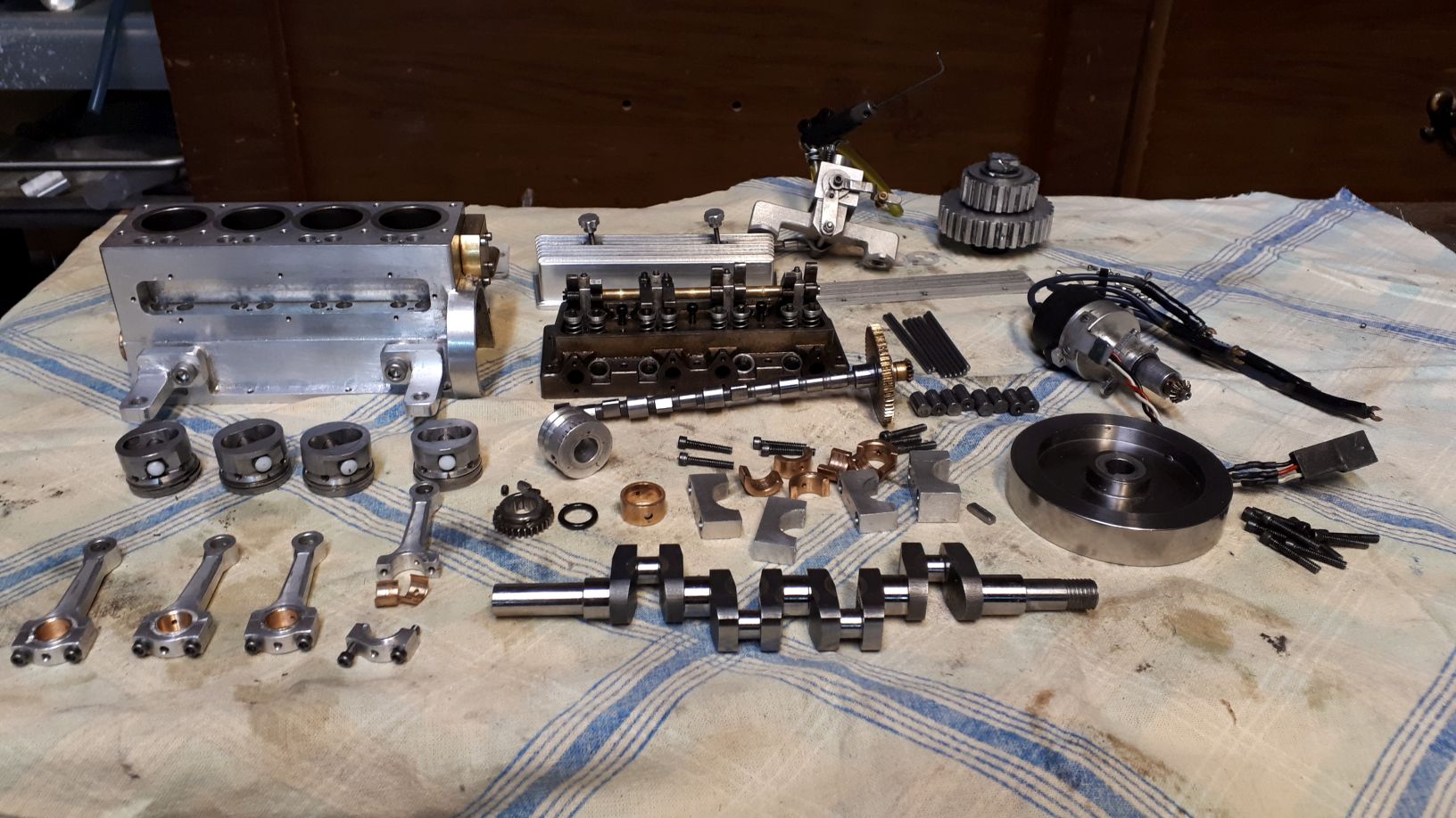
That V8 is awesome! Always been a dream of mine to build one. A massive undertaking though! Maybe the next engine!Think I figured out a more likely scenario.
The one-way bearing did let go but not the bearing itself, I think the outer race slipped in it's housing. The clutch took forever to lock up and got hot, that transferred to the aluminum housing and loosened up the bearing fit. The inner race is keyed to the shaft, the outer is a press fit in the housing.
Hmmm...
That V8 is awesome! Always been a dream of mine to build one. A massive undertaking though! Maybe the next engine!
Interesting on the race slipping.
Don't shoot me down in flames! lol. Bearing mount Loctite? Lots of surface area!
maybe knurl the inner bore, or pin punch it in a few spots, bearing mount locktite, press in the bearing and give it a whirl ????
Enter your email address to join:


