Mini grinder.

Intlwaters

Help Support Intlwaters:

This site may earn a commission from merchant affiliate links, including eBay, Amazon, and others.
Nice work as always Jim, it might be a while until I get to grinding chrome liners again but the pistons will be fairly soon since I'm cracking the stock CMB 67 units.

I think the Dumore wheels are all Norton 32A if they are AlOx.

I want to try some very low taper liners that are ground very round and with the same kind of surface finish you got.  I think I'll to grind them right in the case they'll be run in.
"I WOULD NEVER GRIND ANY PISTON". The reason for this is, the abrasive could possibly imbed itself into the softer aluminum alloy. Think about this!!!

JA
 
"I WOULD NEVER GRIND ANY PISTON". The reason for this is, the abrasive could possibly imbed itself into the softer aluminum alloy. Think about this!!!

JA
I think many of the manufacturers centerless  grind theirs, no?  At least I know K&B used to finish their's this way.

How are the Nelson pistons finished?

Wouldn't grinding allow for tighter tolerances and a better finish in a home shop setting?

I would think a session in my ultrasonic cleaner should clean an aluminum part of any residual grinding dust, no?
 
Last edited by a moderator:
If I needed to grind pistons on a small scale, say 200 pcs. Or less I would thru feed them on a ded-tru.

Holding .00001 diameter size and cylindricity  with proper setup and gagging is easily achievable.

I would not have any fear of grinding grit embedding in the aluminum, although I haven't ground aluminum in at least 15 or more years I had the best luck using a Transor filtration system and synthetic oil for coolant. The Transor filters down to one micron absolute...
 
I think many of the manufacturers centerless  grind theirs, no?  At least I know K&B used to finish their's this way.

How are the Nelson pistons finished?

Wouldn't grinding allow for tighter tolerances and a better finish in a home shop setting?

I would think a session in my ultrasonic cleaner should clean an aluminum part of any residual grinding dust, no?
Terry,

The grinding of aluminum pistons for use in a chromed cylinder of any engine was found to be an invalid process many years ago, for the reason I previously stated. Grinding the piston will not make it any rounder than machining with diamond coated carbide tooling. The roundness will be determined by the quality of the spindle bearings in your lathe. Have you ever checked the runout of the spindle in your lathe? You will need a .00005" increment indicator to read this accurately. 

Nelson Pistons used in any size engine manufactured are machined with diamond coated carbide tooling. You must use diamond coated tools because carbide will not cut the silicon in the aluminum. The tighter tolerances you asked about are done in the home machine shop by grinding the cylinders after the piston's OD & the taper on the top are finished. Now maybe you can understand why I have those .00005", jeweled movement, water & dust proof, shock resistant indicators mounted. I can depend on those indicator to tell me if the lathe has moved less than .00005" and to tell me if I want to move the cross feed or compound .00001". You will want this accuracy in order to fit the cylinders which are being ground to the pistons. 

I have posted several photos of diamond coated carbide machined pistons. Please notice the wear band at the top of each piston. "NO ABC OR AAC ENGINE WILL RUN PROPERLY FOR ANY AMOUNT OF TIME WITHOUT THIS FEATURE!!! You can see this wear band remains visible on the pistons of engines that have many hours of WOT run time. I want to compliment you on the time & effort you have put into learning about our miniature engines. I regret that we do not live closer so that I could bring you into the shop to witness what is done in manufacturing a very high quality racing engine. Recently two people, Dick Tyndall & Alan Hobbs, visited the shop for two days. Ask them what they saw close up!

NOTE: All the pistons in Nelson, Dubb Jet & MB-40 racing engines are made of RSP-444. The alloy you mentioned will grow if it isn't heat treated before final machining.

Jim Allen

P3290005.JPG

P7120037.JPG

P7120038.JPG

P3290008.JPG

P3290013.JPG
 
Last edited by a moderator:
On 2/19/2019 at 12:44 PM, Terry Keeley said:

Not strictly boating related but it's been kinda slow around here anyway.  

I had to true up the spindle on my Clausing mill and used my NSK grinder mounted to my Super 11 to do it.  I'll use the same set up to O/D grind some RSA-431 pistons and eventually re-chromed liners.


I love those Emco-Maier machines!... I had a Compact series lathe/mill combo and sold it- big mistake!...and now I need some 

machinery again. I was saddened to learn that Emco doesn't make the Compact's and Maxi's anymore... just super hobby machines, IMO.

Thanks-

Tim
 
Hey Jim:

I guess the main reason I want to grind them vs turning with diamond or PCD is that once the angle is set for the top taper everything will be locked down.  Plus there's a very precise lead screw in that unit that allows feeding the wheel by tenths easily, I was able to sort of do that with the cross slide on my lathe but you can see from the video I got two tenths one time and the wheel was complaining.

When turning the top taper with a lathe bit the top slide will be used and I just don't trust the action will be tight enough to create the desired results.  Also, at first I will be fitting pistons to an existing liner so being able to remove say 50 millionths of material (0.0001" on the diameter) to get the proper fit will be much easier for me with the grinder than turning!

Thanks for the heads up on the material, I have some RSA-444 I also got from your source, thanks again.  I thought the 444 was for aluminum liners and the 431 worked best with brass?

http://www.rsp-technology.com/site-media/user-uploads/rsp_alloys_microengines_2018lr.pdf

ps:  One of these years I'm going to be down your way and will definitely stop by for a visit!
 
Last edited by a moderator:
If I needed to grind pistons on a small scale, say 200 pcs. Or less I would thru feed them on a ded-tru.

Holding .00001 diameter size and cylindricity  with proper setup and gagging is easily achievable.

I would not have any fear of grinding grit embedding in the aluminum, although I haven't ground aluminum in at least 15 or more years I had the best luck using a Transor filtration system and synthetic oil for coolant. The Transor filters down to one micron absolute...


What kind of grinder would you use?  What about wheels?  I see generally they recommend Silicone Carbide (green)?  Grit?

Did you really mean 10 millionths (0.00001") on the size?  One third of a micron?

Video doesn't come through...
 
Last edited by a moderator:
Terry,

If you were to ask RSP technology if their machine shop made & tested the two materials RSA-444 & RSA-431 for pistons, to be used in a high performance miniature two cycle engine, you would be very surprised at their answer. At Aero Precision Machine we tested at least 100 pistons made of both materials in several different type brass & aluminum cylinders. In all cases the RSA-431 needed to be stress relieved before final OD machining operations. A stress relieve of 405* F for 5 hours worked the best. Although both alloys contain 30% Silicon, a comparison of their respective thermal expansions, thermal conductivities, elongations at 250* C, hardness & ultimate tensile strengths at elevated temperatures, shows the two alloys are very different.  

All of engine parts that are shown in this post were made with my Maximat Super 11 lathe & with my Themac tool Post grinder, mounted to the compound of the lathe. This was before I could afford a full size OD, ID grinder. I purchased both of these machine new & did many modifications before any work was done, including the following; replaced the stock spindle bearings with Timken ABEC 8 (reduced spindle runout from .0002" to less than .0001") preloaded roller bearings; replaced the seal on the back side of the spindle & changed to high quality spindle oil; added many grease fittings to the carriage & the compound; modified & ground the taper attachment ways; ground the cross slide & compound ways; etc. On the Themac Tool post grinder I visited the factory in New Jersey to demonstrate they were using the wrong permanent grease in their spindle bearings as well as the wrong bearings. If I remember correctly the cost of the replacement ABEC 8 bearings was more than $350.00 each way back then. The Chevalier Grinder engineers taught me about permanent bearing greases & how much was to be used to lubricate without causing unwanted heat to develop. Sometimes I would run the grinder spindle 42,000 RPM using small diameter Borazon grinding wheels for an indefinite period of time.

The correct procedure is to finish machine all of your pistons & then fit your cylinders to those pistons. Those solidly mounted  indicators will tell you that you can make several "spark out" passes in a cylinder without moving the cross feed. You will see the ID of the cylinder increase which will change the piston's fit. I have to go now because there is a great deal of work in the shop. I leave you with this question. How would you easily set the compound so that you are positive about the angle you are cutting on the piston's crown? How would you set the compound so that you are positive about the taper amount you are grinding in the chromed cylinder's ID?

Jim Allen

.625 bore barrel carburetor on QD 110.jpg

.625 bore barrel carburetor on QD 112.jpg

cable_collet_clamps_058.jpg

connecting%20rod%20025.jpg

crankcase,%20crankshaft,%20&%20piston%20fixtures%20007.jpg

piston%20cut-away%20001~0.jpg
 
Thanks again for all the great info Jim, you are increasing my success rate considerably before I even start.  RSA-444 it is then!

A toolmaker buddy made the mount for the grinder from Dura-Bar cast iron (1:44 in the video), finish ground it on all sides, scraped the ways in and mounted a precision lead screw from Universal, it's really a nice unit.  It was designed to be able to angle the grinder unit very slightly and lock it down, also as mentioned feeding it fractions of tenths is a piece of cake.  The body of the unit is mounted parallel to the ways and the angle is achieved by moving the grinder on the mount with 10-32 screws on each side.  It is no more accurate than setting the compound just easier.

To get the proper angle I set a carriage stop and using a 1" gauge block to measure the distance traveled an indicator on the side of the grinder can accurately measure the offset per inch of travel.  The MT2 taper was 0.020" per inch, I'd have to dig in my files to see what liner and piston tapers are but they can be easily measured the same way no?  Is there a better way to set the angle?

As mentioned I will be making pistons to fit new stock liners at first so fitting the piston to the liner is what I'll need to do.  In the past I used a helical lap to do this and it worked fairly well but finish grinding should be better IMHO.  Does it really matter if the piston is fit to the liner or the liner is fit to the piston?

My Super 11 is fairly tight but just has the stock spindle bearings, run out in the taper is about 0.0002".  I was thinking of doing all the milling first then mounting the over sized piston to a mandrel held in the lathe, rough turning the O/D then finish grinding the taper and final O/D to fit.  Does this sound reasonable?

I did all this 20 years ago using cast piston blanks from CMB (just turned to size and finished with the helical lap after heat treating) and with this grinder mounted on a dinkey little C5 lathe I ground the chrome I had plated to the stripped liners.  Those were for Picco 45 & 67's and they worked very well, I think Mike Betke is still running some of them today!  Twenty years later I'm a better basement machinist and have a bunch more information to do a better job.  I'm looking forward to trying this 30% Si material!   
 
Last edited by a moderator:
Terry,

If you were to ask RSP technology if their machine shop made & tested the two materials RSA-444 & RSA-431 for pistons, to be used in a high performance miniature two cycle engine, you would be very surprised at their answer. At Aero Precision Machine we tested at least 100 pistons made of both materials in several different type brass & aluminum cylinders. In all cases the RSA-431 needed to be stress relieved before final OD machining operations. A stress relieve of 405* F for 5 hours worked the best. Although both alloys contain 30% Silicon, a comparison of their respective thermal expansions, thermal conductivities, elongations at 250* C, hardness & ultimate tensile strengths at elevated temperatures, shows the two alloys are very different.  

All of engine parts that are shown in this post were made with my Maximat Super 11 lathe & with my Themac tool Post grinder, mounted to the compound of the lathe. This was before I could afford a full size OD, ID grinder. I purchased both of these machine new & did many modifications before any work was done, including the following; replaced the stock spindle bearings with Timken ABEC 8 (reduced spindle runout from .0002" to less than .0001") preloaded roller bearings; replaced the seal on the back side of the spindle & changed to high quality spindle oil; added many grease fittings to the carriage & the compound; modified & ground the taper attachment ways; ground the cross slide & compound ways; etc. On the Themac Tool post grinder I visited the factory in New Jersey to demonstrate they were using the wrong permanent grease in their spindle bearings as well as the wrong bearings. If I remember correctly the cost of the replacement ABEC 8 bearings was more than $350.00 each way back then. The Chevalier Grinder engineers taught me about permanent bearing greases & how much was to be used to lubricate without causing unwanted heat to develop. Sometimes I would run the grinder spindle 42,000 RPM using small diameter Borazon grinding wheels for an indefinite period of time.

The correct procedure is to finish machine all of your pistons & then fit your cylinders to those pistons. Those solidly mounted  indicators will tell you that you can make several "spark out" passes in a cylinder without moving the cross feed. You will see the ID of the cylinder increase which will change the piston's fit. I have to go now because there is a great deal of work in the shop. I leave you with this question. How would you easily set the compound so that you are positive about the angle you are cutting on the piston's crown? How would you set the compound so that you are positive about the taper amount you are grinding in the chromed cylinder's ID?

Jim Allen
 
"As mentioned I will be making pistons to fit new stock liners at first so fitting the piston to the liner is what I'll need to do.  In the past I used a helical lap to do this and it worked fairly well but finish grinding should be better IMHO.  Does it really matter if the piston is fit to the liner or the liner is fit to the piston?" What happens if those stock cylinders do not have the correct taper, the wrong finish or they are out of round? Why go so far & only do half of what needs to be done? If it was an engine for putting around the lake, I think this would be okay. However, your going to use these engines for record trials. Yes or No. 

Your method for setting the compound certainly would work. "I'd have to dig in my files to see what liner and piston tapers are but they can be easily measured the same way no?  Is there a better way to set the angle?" What if there was a way to use a .00005" indicator over a distance of approximately 2.500" to set the compounds taper amount, do you think this would be much more accurate because of the longer distance?  The method I use requires no gage block & no files to dig into. Think about this some more.

"I was thinking of doing all the milling first then mounting the over sized piston to a mandrel held in the lathe, rough turning the O/D then finish grinding the taper and final O/D to fit.  Does this sound reasonable?" NO! You will need to cut that taper at the top of the piston & cutting this will change the fit in the cylinder. How do you hold the piston to finish machine both the OD & the taper on the top? How do you insure that the wrist pin hole is square to the pistons OD? 

Terry, I do not intend to be mean or facetious. However, the proper techniques for making just the one part, such as a piston, will require some thought.

Jim Allen

cable_collet_clamps_006.jpg

cable_collet_clamps_011.jpg

cable_collet_clamps_012.jpg

cable_collet_clamps_013.jpg
 
Last edited by a moderator:
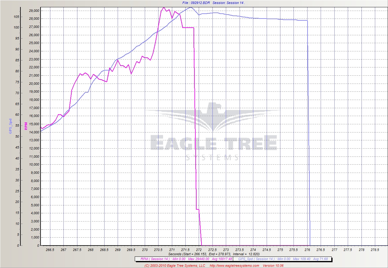
Yup, as mentioned I eventually want to get back to re-chroming liners and want to try some different tapers but before I get to that I want a dyno to accurately measure if I'm gaining anything or not.  The main reason I want to make some pistons now from this material is I'm getting cracks in the stock pistons, even had one let go and seize the motor  at 29K+, pretty spectacular:

 
093012-11trim.jpg


Yes, setting the compound taper over a longer distance would certainly be more accurate but using a gauge block to get this distance is very accurate, is it not?

The piston would be turned straight (no top taper) to about 0.010" oversize, all the internal milling done leaving a step in the bottom, then the wrist pin hole would be put in with a V block type mandrel in the lathe, lapping to final size.  Circlip grooves would be cut as well at this time.  This is how I did them before, it worked very well.  Or I might do it on the mill this time, set up properly in  a V block would make sure it's right.

It would then be mounted on another mandrel that holds it on the step with an arm to tighten down holding it from the wrist pin on the inside.  Indicate it in the 4 jaw and it's ready to finish grind.

Grind the straight part very close (a couple tenths) to size then grind the top taper.  Fit the sleeve.  Go back and forth between grinding the straight part and taper until the desired fit is had.  Tedious, yes!  But to fit a piston to an existing liner what option do you have? 

There's more than one way to skin a cat, not that the cat would care tho... :unsure:
 
Last edited by a moderator:
Hi Terry,

The machine I was referring to earlier was a Mitsui 8x18 surface grinder with a Ded-Tru grinding attachment mounted on it.

This combined with an opptidress wheel dresser is the standard in the mold grinding industry for grinding core pins ect.

It is a very cost effective means of precision I.D. O.D. grinding.  With this attachment you can also through feed and in feed c-less grind.

Before my father purchased a proper C-less grinder for small diameter close tolerance parts I taught myself how to C-less grind with a Ded-Tru. The only drawback is that in order to get true roundness you need a roundness gage which is a costly piece of equipment for the average hobbyists.

this gage is necessary to view the shape of the O.D. On a polar chart and then to make the necessary blade adjustment to reduce the out of round condition.  Simply using a mic or an indicating mic is unacceptable as it only checking between two points and cannot determine lobbing. The roundness Gages that I used are made by rank Taylor Hobson and use an air bearing for the spindle and electronic gage heads with adjustable pressure. I believe the ones I used were guaranteed to be accurate within  .000002 inch.

on the other hand I can see Jim's way of manufacturing the piston as a very cost effective way of sizing the O.D. Of the piston.

many years ago me and my father visited Moore Special Tool Company to purchase a Jig grinder. During this visit we got the grand tour of the facility.  One of the projects  that caught my eye was the diamond turning of aluminum on an air bearing for an optical application.

i believe if you go to their website you can find the very impressive videos of this process.

With this process you can achieve incredibly low roundness and micro finish. It might be possible to mount an air bearing in your lathe as a cost effective solution to rebuilding you're lathe spindle..... Maybe Jim would have an idea on this as I have never turned this type of aluminum in a lathe and I don't know how easy it is to cut.  It maybe possible in the future for my coworker to make some custom PCD cutting tools on our laser for testing purposes.
 
Back
Top