Terry,
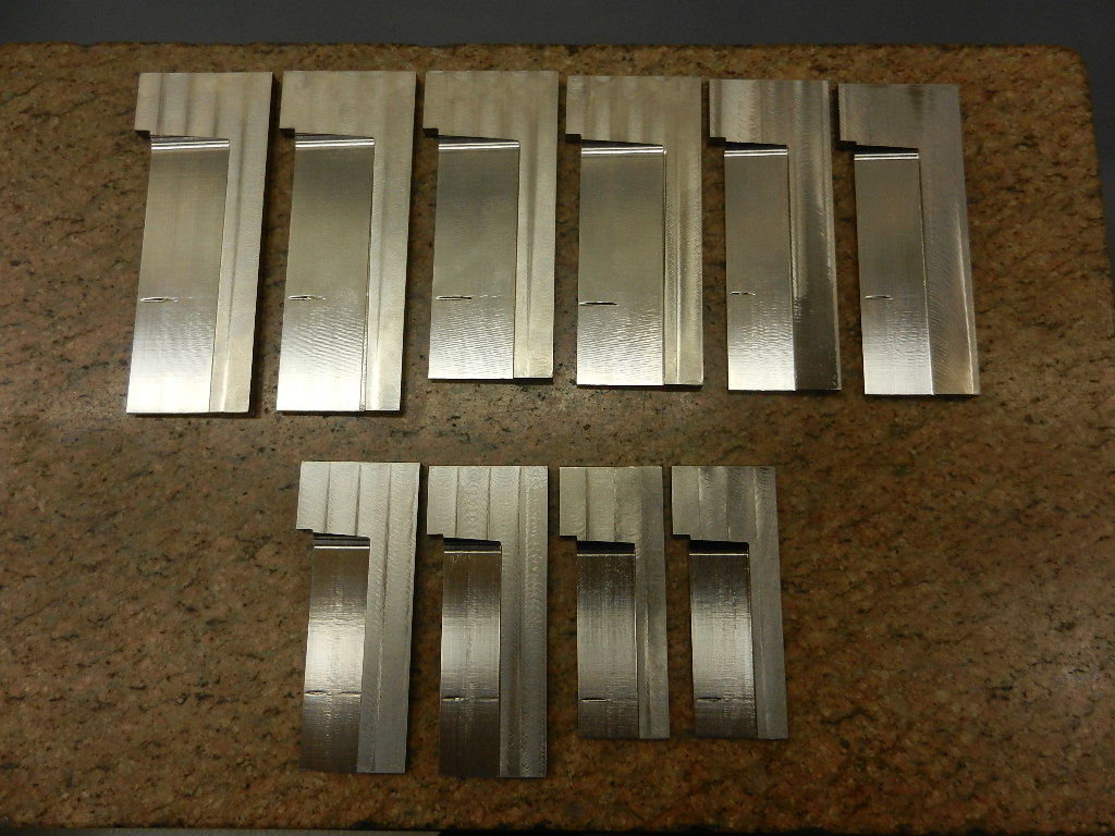
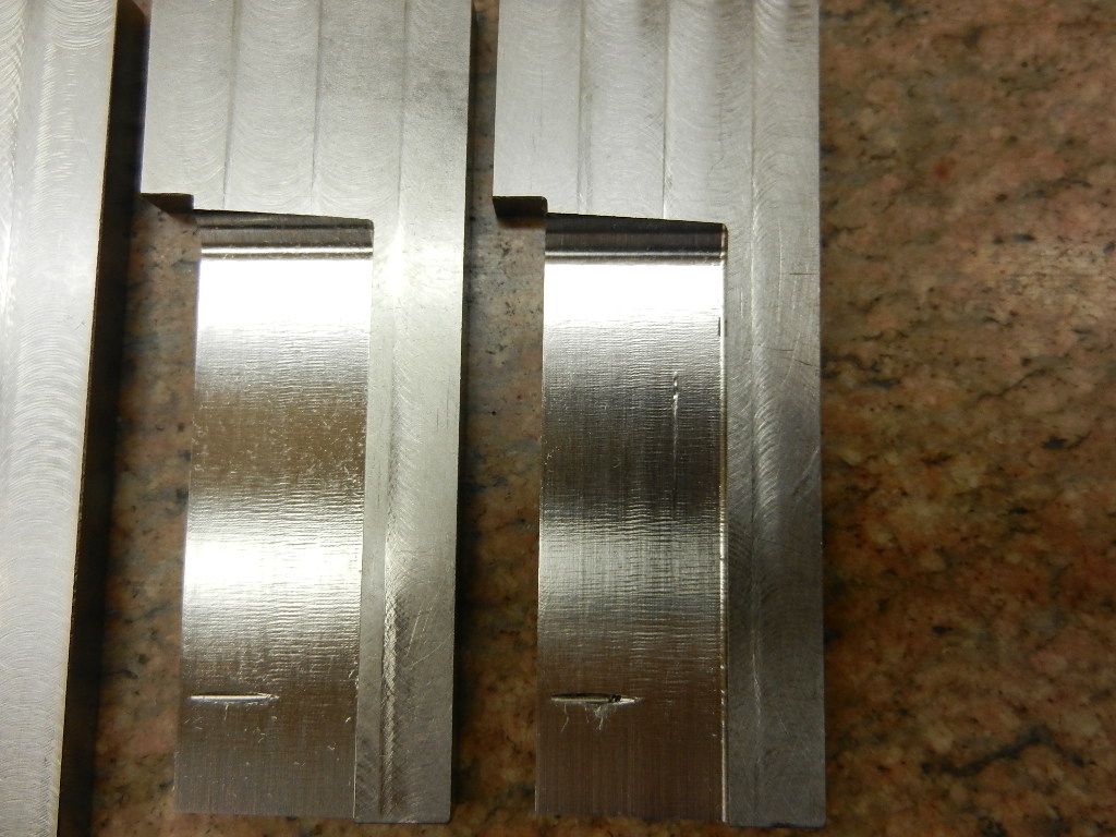
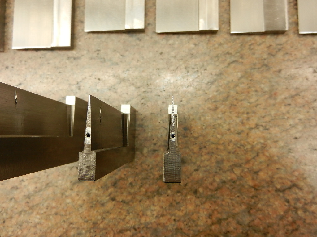
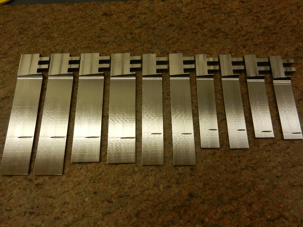
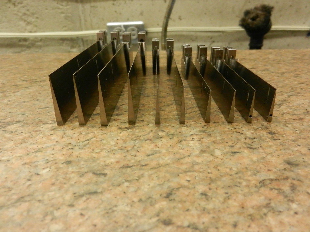
The fixtures are not adjustable. When I need a smaller width rudder blade, I reduce it's width while it is still in blank form on both ends. All of my blades have tapered back edges which are done in blank form & I drill the water passage way last. Locating the water passage way is easy because the blank it still a rectangle on both ends & it can be easily mounted on a precision angle plate. I also press a hardened steel piece in the hole where the shear pin is to be mounted. Different width wedges, on identical blade shapes, will produce different amounts of lift to the rear of the boat when the speed is constant. This is also true for wedges of same width & different lengths.
JA