New projects for this year.

Intlwaters

Help Support Intlwaters:

This site may earn a commission from merchant affiliate links, including eBay, Amazon, and others.
That looks great Lohring!!

What load cell is that?
Thanks, it's a Measurement Specialties 10 pound compression load cell. After calibration with some electric motors, I hope to work with some local hydro racers on a 12 engine program.

Lohring Miller

Let me know how it works. that is the one that will link up to a Eagle

Tree analog interface card.

Can't beat that price ether.

Did you preload the cell with the weights that I see on the cradle assembly?
 
Yes, the idea is to load the load cell close to full scale and have the dyno torque unload it. I'm hoping that system will avoid vibration problems. The other weight counterbalances the magnet rack so moving it doesn't change the load reading. The dyno has considerable inertia, so it could double as an inertial dyno for smaller engines. Replacing some disks with a steel flywheel for a combination brake/inertial dyno is my next thought. I think the Eagle Tree logger has too slow of an update rate for that, though. It's time for some real testing to see how it works.

Lohring Miller
 
I see you will make the break unload the cell.

How much of a refresh rate do you think will be needed?

the logger will do 10 times a sec.
 
Ten Hz is once every 50 revolutions at 30,000 rpm. The Performance Trends data logger we use on our inertial dyno has a 100 Hz update rate. That's once every five revolutions at 30,000 rpm . We see scatter on our dyno with higher rpm (over 20,000) engines. I think this has more to do with the rpm sensor than the update rate. I'll check the data to see how the Eagle Tree does with it's Hall effect rpm sensor. It may be OK. I'll need to setup a spread sheet to calculate the power in any case, especially if it uses both brake and inertia.

Lohring Miller
 
I used the photo sensor at first in my boat and it gave good reading. But it was hard to keep the white paint on the flywheel with all the fuel mess.

The hall sensor dose give erratic reading some times. But I think this gets worse after many runs and all the vibration in the boat.

Also the mount in the boat was a little flimsy.
 
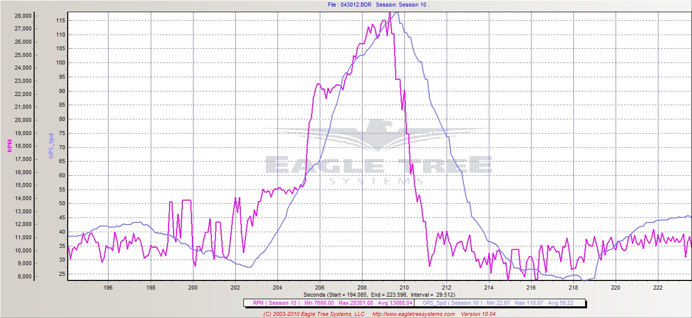
Rpm data's a little ragged at 10HZ, the V4 logger can do 50Hz but that setting isn't compatible with the LCD display so I haven't tried it yet...

043012-10trim.jpg
 
I have both loggers but I don't think the analog to digital card will work on the V4 to log the load cell.

I will give them a call and see if it can work with the V4.
 
Back to flow visualization. This idea is the best easy flow visualization I've seen.

"A rosebud torch directed into ports can show a lot of the flow characteristics, particularly when comparing changes or other ports. Directing the torch towards various areas of the ports can show how the flow is affected by different shapes and sections. A larger torch would be nice, and were one so inclined I can imagine a dedicated multi tip torch to see interaction between ports."

The torch is aimed into the transfer passage and moved to look at the effect of wall shape. You can see the effect of the angle of the top of the transfer by looking through the exhaust. The picture below is the resuly of Photoshopping two flow pictures together.

Lohring Miller
 
Last edited:
Back to flow visualization. This idea is the best easy flow visualization I've seen.

"A rosebud torch directed into ports can show a lot of the flow characteristics, particularly when comparing changes or other ports. Directing the torch towards various areas of the ports can show how the flow is affected by different shapes and sections. A larger torch would be nice, and were one so inclined I can imagine a dedicated multi tip torch to see interaction between ports."

The torch is aimed into the transfer passage and moved to look at the effect of wall shape. You can see the effect of the angle of the top of the transfer by looking through the exhaust. The picture below is the resuly of Photoshopping two flow pictures together.

Lohring Miller
That is a great pic. You must remember that the streams react to one and other.

There was a paper I red on how a stream will pull one to the other. Kinda like if you fill a void with a stream it will draw the opposing stream to it. This happens around a circular object.

It would be cool to fill each port at the same time with a torch.

Also some die in the liquid when doing the test on the wet flow bench might give some good results.

Florescent die and a black light might do it.
 
Here is my dyno


it is a inertia dyno and works very well for this type of engine.

The flywheel is a 10kg 11.8inch steel plate.

Gearing is 4.8-1

The graph before the pull is with longer pipe setting..
 
That is a very simple setup. I like that.

Any problems with the belt drive?

Do you use a one way bearing to couple the Eng to the wheel?

Kinda funny some said a belt would never run at that speed.

A video is worth a thousand words.
 
Last edited by a moderator:
No, belt drive works perfect

Yup, one way needle bearing.

I have done 25k rpm on the engine, 5,2k on the wheel without any problems.

Yes simple and good, only an rpm sensor at the flywheel. The load is the same every time you do a pull, so you se difference in engine setups very easy.

I had a water brake before, but it is very hard to control when the pipe comes on, and the load is different from what you have in a boat. Did not get any good results from it.
 
As I've said in the past, an inertial dyno is by far the simplest way to do a lot of quick testing. See the picture below. We've run it since 2003. We run a centrifugal clutch. Do you have problems without it? Other inertial dyno builders found that one way clutches didn't work with the vibration and high rpm of our engines. It looks like you are running the Performance Trends software. Is that true?

Lohring Miller
 
No, i dont think i need a centrifugal clutch, it is easy to start and runs fine on idle. After the pull i can let the engine back on idle or stop it while the flyweel is spinning.

20mm one way needle bearings can be used over 20k rpm, my flywheel does not spin faster than 6-7k rpm.

The one way bearing have never been a problem

You need to have a surface harder than 50 hrc for the needle bearing, i used hardned 2541 steel.

Yes i do
 
As far as seeing wet flow patterns, a strobe light will work well. get one with a speed adj., then you can synch it to the droplets speed, & freeze frame them. you will be able to watch them change shape, elongate, combine & separate as they change directions & speed. used to use a timing light on car carburetors, was amazed at the detail i could see!
 
As far as seeing wet flow patterns, a strobe light will work well. get one with a speed adj., then you can synch it to the droplets speed, & freeze frame them. you will be able to watch them change shape, elongate, combine & separate as they change directions & speed. used to use a timing light on car carburetors, was amazed at the detail i could see!
That I will have to try.

Dam the wife will think I am having flash back with the vacum runing and the strobe. :blink:
 
The belt drive system changes every thing as far as what will work and not work.

A hydraulic or fluid power pump would work well with a belt drive.
 

Latest posts

Back
Top