Mounting a .82 K&B on a 360 HTB

Intlwaters

Help Support Intlwaters:

This site may earn a commission from merchant affiliate links, including eBay, Amazon, and others.

gratte-tout

Well-Known Member
Joined
Jan 28, 2008
Messages
166
Hi all,

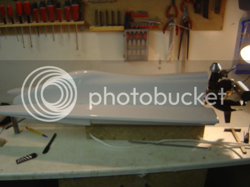
As my .21 twin starts to be performant, I take time to start the building of the 360HTB hull I bought there's few months ago.

It will be mounted with a special edition K&B, a 80 one, if you have informations about it, I'm interested, I don't know anything about this engine, almost the basic settingsof it.

DSC04981.jpg


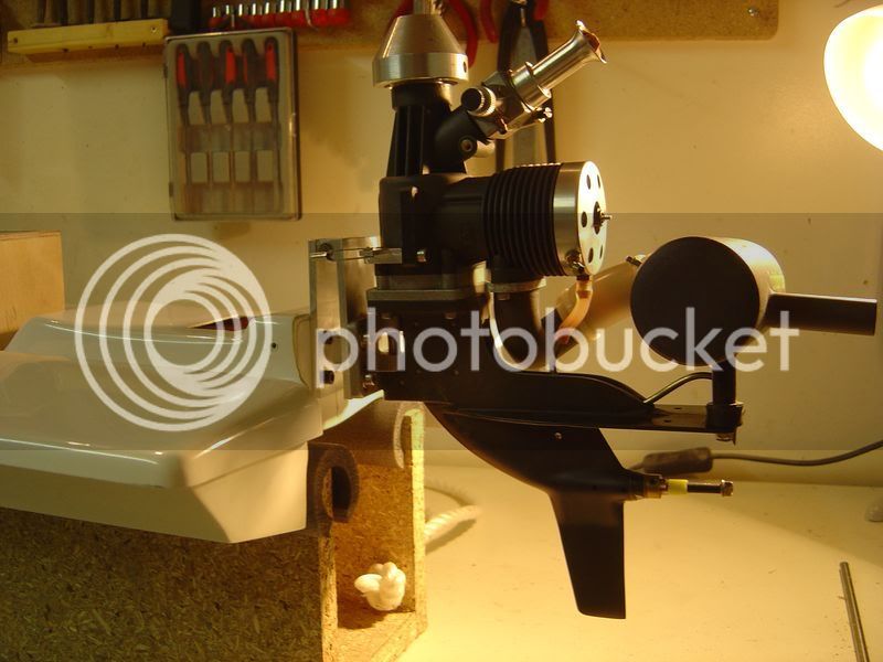
Because a friend conviced me the interest of a trim system on such a hull, I decided to think about a simple system to angle the engine with my radio when necessary.

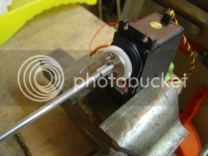
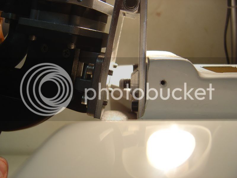
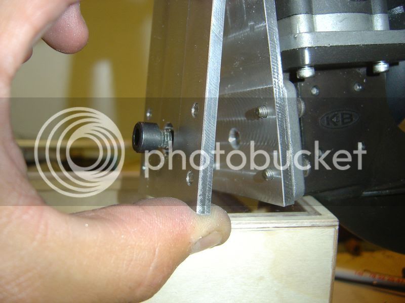
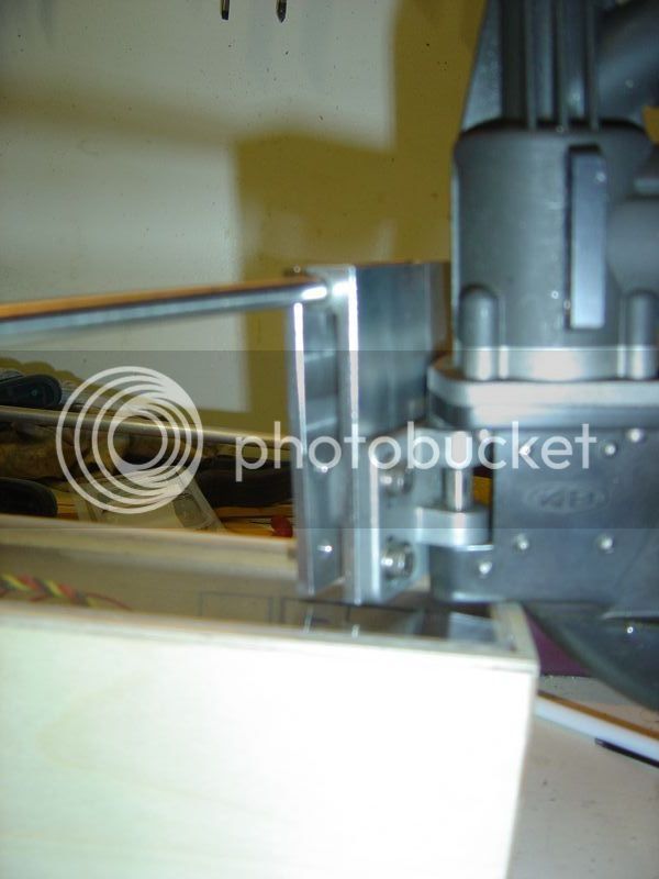
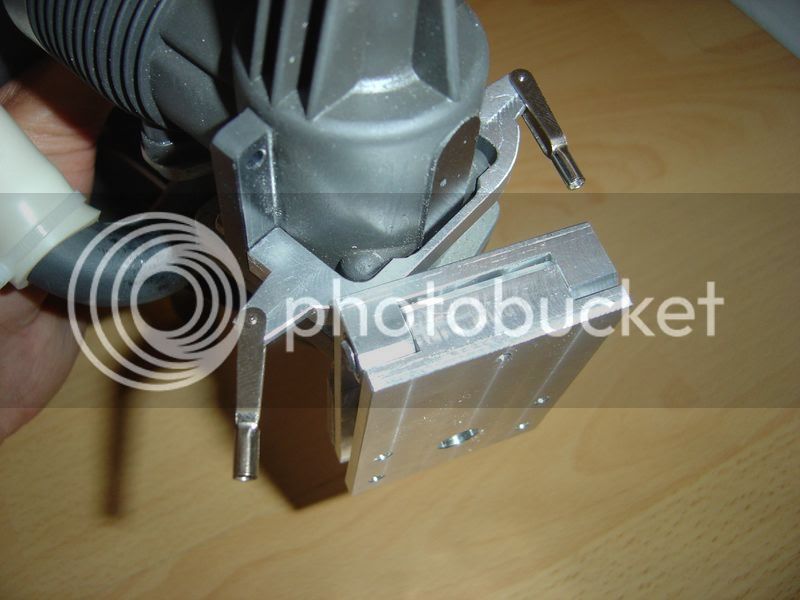
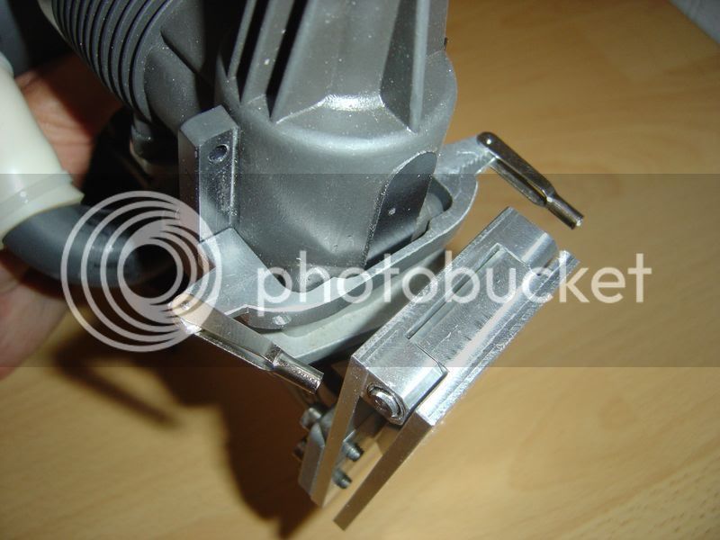
After triying to design as more simple as possible the system, I decided to use a bracket with a screw, moved with a sail servo like the Hitec HS855 (3.5 turns). When the servo is turning, the screw with a 1.5 mm pitch is pushing the bracket where the engine is screwed.

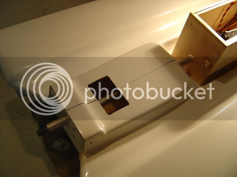
The two brackets are assembled so that when the engine is angled, the steering rods are not pushed or reverse. The rotation location of the two brackets is on the same plan than the steering rods.

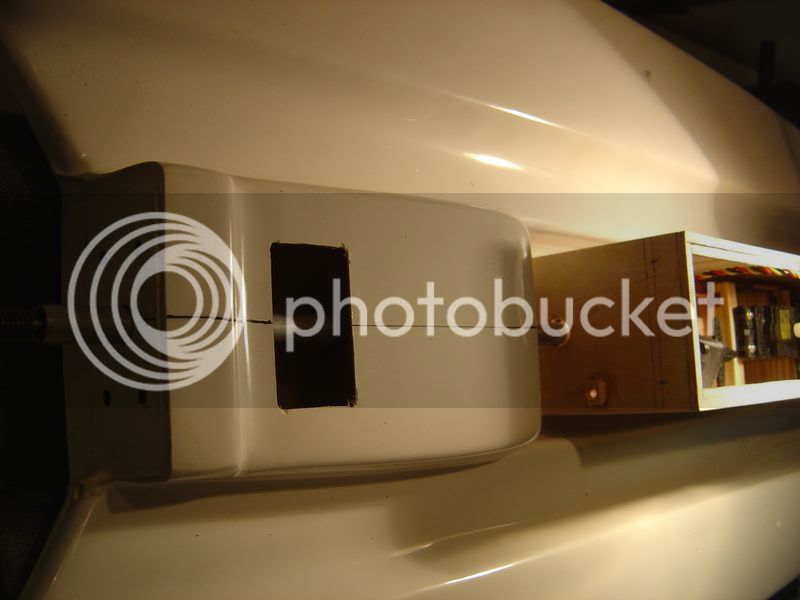
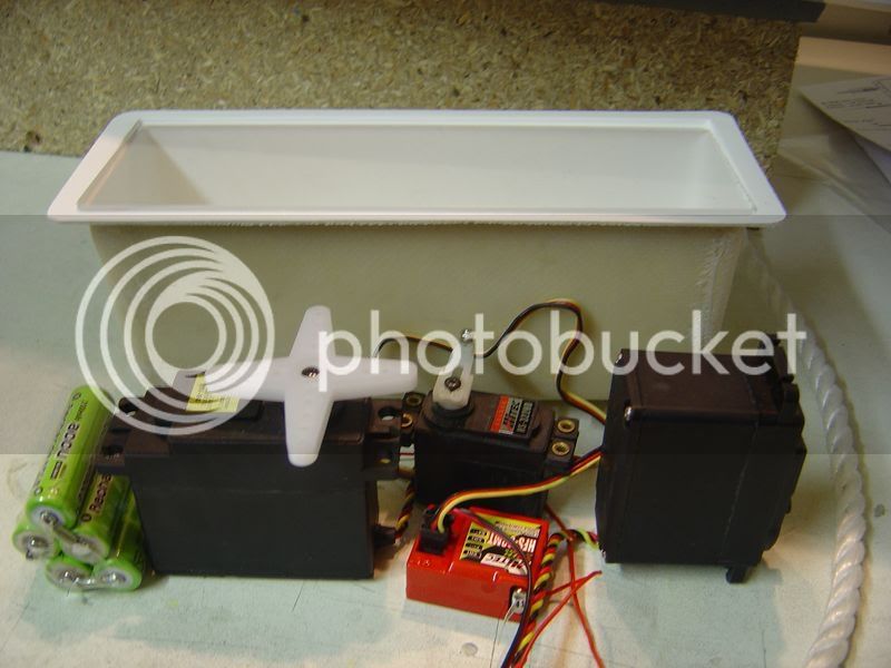
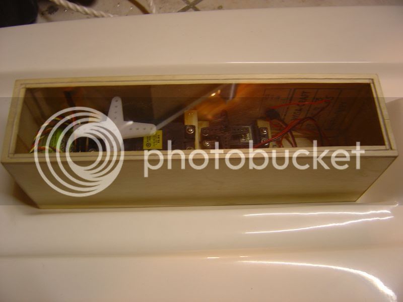
I had to built a new radio box, the one coming with the hull didn't allow to put another big servo, almost I don't wnat to put it on the same position than the steering one.

The old radio box with the servos I have to put :

DSC05067.jpg


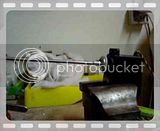
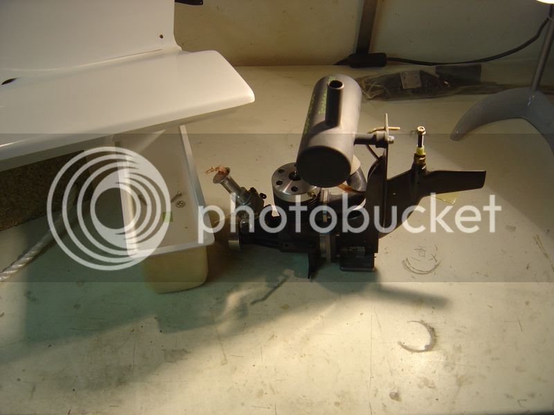
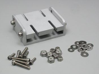
The designed trim system

Screen_4.jpg


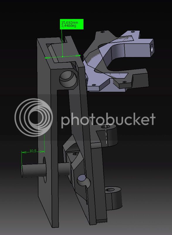
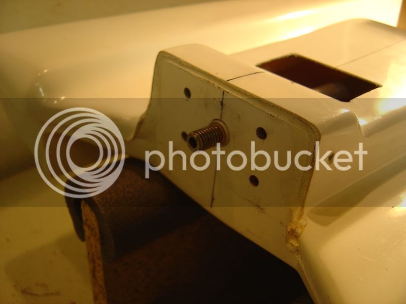
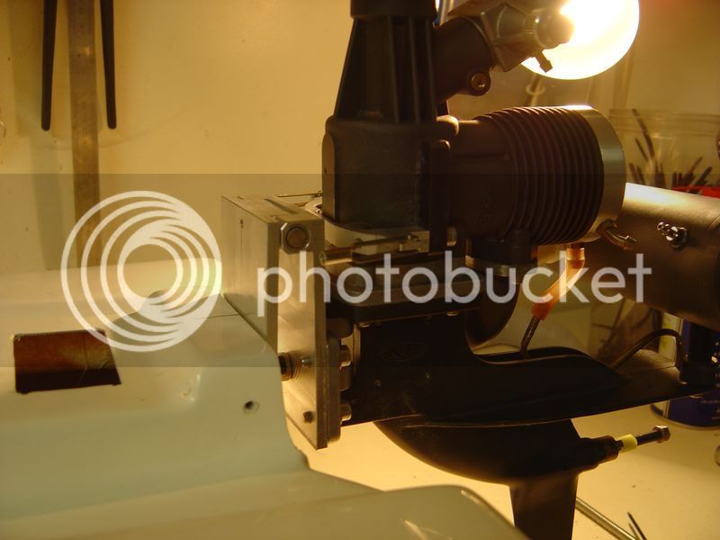
This picture showed I had to machine a new steering bracket, the plastic one was not compatible with the trim brackets.

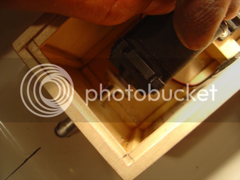
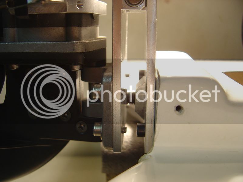
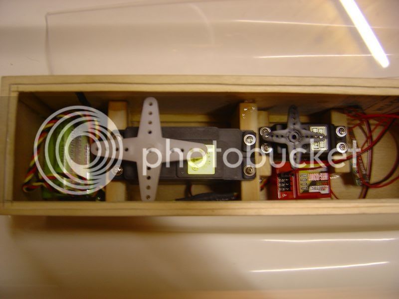
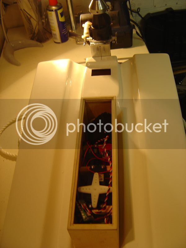
After CAD pictures, machining and gluying!
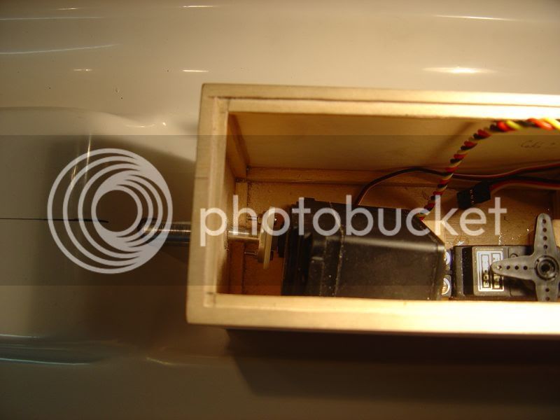
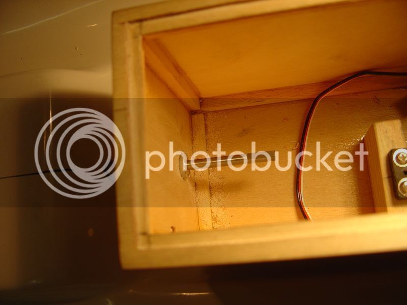
The new radio box :

DSC05259.jpg


DSC05260.jpg


DSC05274.jpg


.
 
Last edited by a moderator:
Then, the brackets of the trim system. A teflon part will be put on the end of the threaded axle, to put safely the engine bracket.

DSC05264.jpg


DSC05262.jpg


New steering bracket :

DSC05268.jpg


DSC05266.jpg


DSC05275.jpg


DSC05272.jpg


DSC05273.jpg


To be continued..

P.S. : i'm interested by the basical settings of such an engine, I'm using a low nitro fuel (16%) and 18% oil.

Thanks
 
Then, the brackets of the trim system. A teflon part will be put on the end of the threaded axle, to put safely the engine bracket.
DSC05264.jpg


DSC05262.jpg


New steering bracket :

DSC05268.jpg


DSC05266.jpg


DSC05275.jpg


DSC05272.jpg


DSC05273.jpg


To be continued..

P.S. : i'm interested by the basical settings of such an engine, I'm using a low nitro fuel (16%) and 18% oil.

Thanks


Fabrice,

Im impressed with your projects, as always.

But i see one fatal flaw in your trim system.

Correct me if im wrong,, but

The hinge pin should always remain 90 degrees to the ride surface. Moving that pin at a angle will cause the hull to handle poorly in the turns. It will either hook, or porpious.

I figured i would let you know before you got any further.

Alden
 
I would tell you if you're right or not if I could understand what you're calling a hinge pin..

Could you try please to explain me this?
 
Do you figure that when I'm going to angle the engine, the hull will not turn correctly?

In fact, the engine will noty be massively angled.. I will angle it for 4-5 degrees max, from -2.5° to +2.5°.

But I'm not sure you told me that.

My friend told me it's very sensitive, and almost the prop is more far from the transom than the original mounting.
 
Do you figure that when I'm going to angle the engine, the hull will not turn correctly?In fact, the engine will noty be massively angled.. I will angle it for 4-5 degrees max, from -2.5° to +2.5°.

But I'm not sure you told me that.

My friend told me it's very sensitive, and almost the prop is more far from the transom than the original mounting.


the hinge pin is the pin where the engine pivots/turns side to side.. that pin should be 90 degrees to the ride surface at all times..

if the pin is not 90 degree's the engine will change trim when turned,,, causing hooking or porpoiseing in the turns depending on which way the pin is angled....

alden
 
mr. tim duggan or mr. jerry wyss could probably confirm my assumtion.... i am going through this with a ts2 tunnel i just purchased...

alden
 
Ok, I think i've got it : you are telling me that basicly that in order to angle the prop, only the prop shaft should be angled, keeping the stering pin at 90° from the ride surface. That's it?

I have a question too : do you know one mounting system allowing to angle the prop shaft without moving the steering pin?

Every engine mounting systems I saw are made as mine, I mean that every one allows to angle the engine, but they are also moving te hinge pin, so it's no more at 90° from the ride surface...

But I understand what you mean, I will draw something to figure the differences to check your thinking.

In fact, the hinge pin should be in front of the angle pin, instead of beeing behind. This should allow to angle the engine without moving the hinge pin. I don't know if there's a difference from a kinematic point of view.
 
Ok, I think i've got it : you are telling me that basicly that in order to angle the prop, only the prop shaft should be angled, keeping the stering pin at 90° from the ride surface. That's it?
I have a question too : do you know one mounting system allowing to angle the prop shaft without moving the steering pin?

Every engine mounting systems I saw are made as mine, I mean that every one allows to angle the engine, but they are also moving te hinge pin, so it's no more at 90° from the ride surface...

But I understand what you mean, I will draw something to figure the differences to check your thinking.

In fact, the hinge pin should be in front of the angle pin, instead of beeing behind. This should allow to angle the engine without moving the hinge pin. I don't know if there's a difference from a kinematic point of view.


exactly,,,, pin should be infront of your angle/trim system..... my thunder tiger,, and i beleive o.s engines are trimmed/tilted after the pin....here is a picture of one of my thunder tiger outboards.... notice the slotted top hole... to tilt the engine but the pin will remain 90 degree's to the ride surface...
 
Last edited by a moderator:
I've checked at Mecoa their mounts.

They are exactly as I designed mine.. The hinge pin is at the bottom of the angle pin.. So when you are putting an angle on the mount, the hinge pin is no more at 90° fron the ride surface

pra35mount.jpg


I think i'm going to use mine like it is now, and if there are any problems I will be the first advertised..

James, you are fine at tunnel hull, what do you think about it?
 
is it a 81 or a 82, try mecoa.com, really nice work on the trim plate.
tim
Ho, are you talking about my trim plate or mecoa ones?

I checked, my engine is a .82 one, and I should open the needle valve from closed for 3.5 turns.

I will start with 4 turns, as I run a less nitro fuel.

edit : I have only one bolt on the prop shaft. I don't know it size, and here in europe, it's very difficult to find imperial bolts..

Can anyone give me a link for a store selling such bolt (with plastic "brakes" please) or send me one or two, in exchange with metric ones, wich should be difficult for you to have..

Thanks.
 
Last edited by a moderator:
Wow that is nice work on your trim plate.

How high is your motor going to be on the boat? Where do the holes on the center line of the lower unit end up ?

Cause if they are to high the boat will not handle at all.

HTV has a motor mount that has a 3rd channel trim built in to it. He got the it from Ernie.

Just don"t want you spending all day at the pond and not having your boat run right.

Let us know how it works.

Richie R
 
Fabrice, you are fine. Almost all aftermarket mounts work just like the one you have. I run an adjustable mount on one of my boats also, and the pins moves just like yours. The set-up I use came from Mic (HTV Boats), and it works great. Like you mentioned, you are only talking 2 degrees MAXIMUM movement, but will be more like less than 1 degree. The OS and the Thunder Tiger have a stationarly pin that remains 90 degrees, but MANY engines use the above type mount with no trouble.

I dont like knocking boats, but the TS2 is very well know to have a nasty hop. 98% percent of them that I have seen have this problem. Its the boat, not the mount.

Carry on with your works, its really nice as usual!

~James
 
I would rethink the mounting of the muffler. The lower unit cav plate is made from cheap cast aluminum. It will not hold up the the wieght of the muffler after you run it awhile. It will break. You need to reinforce it with some stainless steel.

Mike
 
I keep the holes on the plates so the engine is exactly where it's advised to be on the hull's manual : actually, the prop shaft is aligned with the deeper point of the hull.

I know I will have to change this depth, I kept the center of the engine plate so that this position is the middle one, I could down or up the engine one 3-4 mm on each way.

James has exactly (and better than me :D ) explained the settings I will have, not more that 5 degrees, 2-2.5 on each way. To use the full range, I will have to use the stick of my radio, but I think setting the angle with the trim of the way will be enought.

Matthew, I don't know, the engine I bought was modded at a factory, I don't even know from where it comes, if anyone knows, I'm interesting..

The muffler seems to be a special torque one, and it's mounted on a rubber

I think this hull will be a real dragster with suc an engine, I'm very intersting about seeing it running.

In one or two weeks, at the pond! Maybe next week-end.
 
so there ya go,,,, james confirmed it,,,, the 90 degree pin setting applies to my engine and not yours,,,,, sorry for making you second guess yourself....ive only run thunder tiger outboards so i didnt realize they were different....

carry on with the awsome fabrications.... look foward to seeing it complete....

alden
 
Not a problem ;)

Thanks for your answer, it could be usefull on another boat, I will remember this.

Tonight some news :

I mounted the sail servo with its screw, I had to done another one, I welded a part of a stainless steal screw, but not centered fine, so the servo forces, it's working, but not as free as I wonder. The system still be validated. I just have to machine a crew after wleded a round stick on the 4mm shaft wich is the shaft the sail servo actionnate.

This is the head I had to machine on the sail servo, it has to gives the rotation but ust be free on the axle of the shaft, that's why it's milling by a 3mm mill, and the shaft has the same one but in male.

DSC05276.jpg


Put on its position (almost..) in the radio box :

DSC05278.jpg


DSC05281.jpg


I had to drill a 10mm hole in the hull, to pass under the fuel tank.

DSC05279.jpg


DSC05280.jpg


As the shaft is in a 10mm tubing with bronze bushings, and this tubing beiing glued on the hull, the hull should still be sealed

The driver, on trim shaft side :

DSC05282.jpg


The aluminium tubing goingt throught the transom :

DSC05283.jpg


When everything is on its place, with the little teflon pusher on the head of the screw :

DSC05285.jpg


DSC05284.jpg
 
Do yourself a huge favor and run 40%. That engine will not run well at all on such low nitro. If thats all you have to work with then so be it, just a little tid bit that will make a huge difference.

Larry Jr.
 
Back
Top