David Ashcroft
Well-Known Member
- Joined
- Jan 26, 2014
- Messages
- 1,670
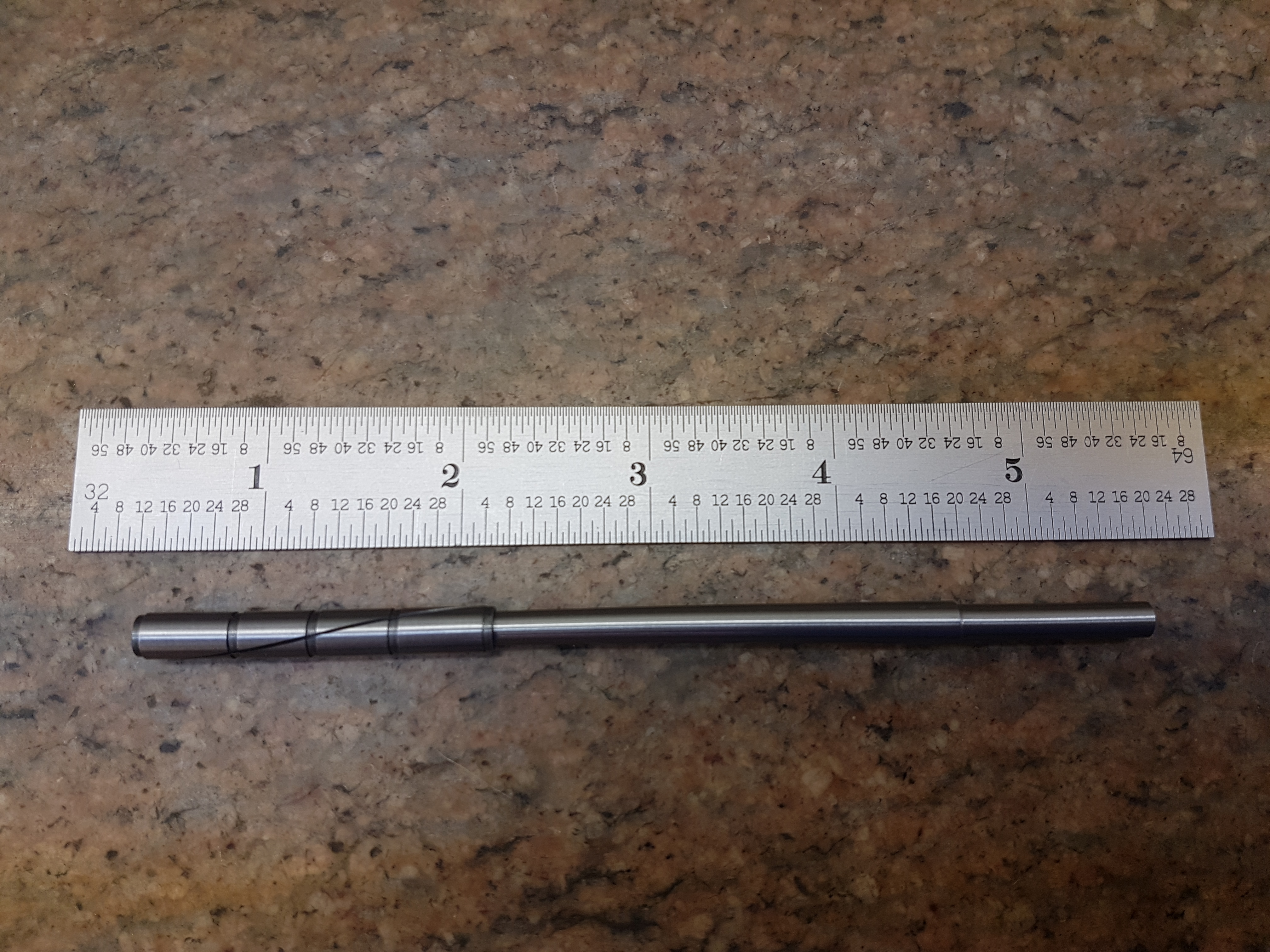
Anyone have a k&b 1.0 cube conrod would like to have a few machined


What do you use to clearance it, and how much? Assume only the crank end or also the piston pin end? Sorry, I'm a shade tree machinist. Thnx, James


Very nice equipment Ricky!
On the bigger engines (45's and up) we went for 0.0015" - 0.002" clearance for the bottom end of the rod and 3-5 tenths for the top.
I'm going to try this helical lap and non imbedding compound to finish some wrist pin holes in pistons:
https://www.helicallap.com/
James,Thanks to all for the input. I'll likely make a dowel with 600 - 1000 grit on it and shoot for the 1/32nds clearance.
Lol, fair point - i was hoping that showing the logic may help figure out what kind of clearance may be required but i fully understand that without the specialist tools its not a whole lot of helpJames, get you shade tree micron reader out. Or I an borrow you mine.. send 400 dollars for 600g sand paper and a plastic dowel and some note book paper to Grimracer..
Just kidding Ricky..LOL..
Love to see how its done.. but not sure how this helps James.
(hand wave) Move along.. the droid you are looking for is not here.............. move along.. move along!
Grim
Thanks.Very nice equipment Ricky!
On the bigger engines (45's and up) we went for 0.0015" - 0.002" clearance for the bottom end of the rod and 3-5 tenths for the top.
I'm going to try this helical lap and non imbedding compound to finish some wrist pin holes in pistons:
https://www.helicallap.com/
Thanks.
I had to convert to metric to compare but thats 38-50 microns. Thinking about it - within reason i think its always safer to lean towards a bigger clearance. Too tight will always end in disaster
Terry, didn’t Paul Richardson use a spherical broach to size his RPM rods? It worked for the K&B series 70 pylon rods I made in the early days.
John
Rod you don't think that oil gets forced in through the oil holes in the rod as the rod is spinning around at 20 K rpm ?I have tried reamers and that is not the way to go.....Leave the wristpin end alone.....
I just use a hone made of a piece of turned down slotted nylon dowel and some 600 wet and dry sand paper wrapped around it , and a cordless drill....
Remember , when the motor is running the conrod is always in compression.....
You have to reduce that contact patch between the rod and crankpin to reduce the friction causing heat....That is why a lean run will spin rod bushings....
These motors all have tramp oiling systems , meaning no pressure oiling system.....you need some clearances to get oil onto the crankpin and rod bushing...
The oil holes in the rod bottom are to let oil out not force oil in.....
Really the only need for the bottom of the rod is to start the motor and to clean it out....
When the motor is running the crankpin never sees the bottom of the rod bushing......Heat is what kills rod bushings.....
There are no set numbers for clearances....
I hold the rod on the crankpin and when I get the wrist pin end to rock up and down on the crank pin about 1/16" of an inch I call it good....
I polish the hell out of the crank pin with a buffing wheel and red jewelers rouge .....
If you are replacing a rod that has spun a bushing you have to make sure you get all the residual bronze bushing material off the crankpin...
That residual bushing is hard to see.....I check he crankpin with a 10 power eye loupe .........
Harbor freight has a good loupe set for about $5.00.......
If you don't get that residual bushing material off , you will be replacing the rod again in about one minute....
Anybody......I know all this can be confusing so........if you have any questions....
Call me
1-715-926-6096 landline
1-715-495-5025 cell
When a rod gets loose that is when it is good......
I believe the crankpin is the eye of the rotating fan resulting in a low pressure area at the crankpin sucking oil in......I believe that the holes let the oil out....Rod you don't think that oil gets forced in through the oil holes in the rod as the rod is spinning around at 20 K rpm ?

Enter your email address to join: