- Joined
- Jan 2, 2005
- Messages
- 1,049
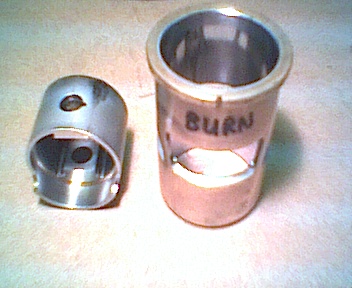
David, I have 2 stock 101 new p/l to check I'll get back to you and tell you were they fall, stock with no lapping and honing. You are doing good building custom pistons for the 101's. The piston walls are thin and not much material under the wrist pin boss. I have also broke one. Engine had just hit the pipe, and it did not stick, it just broke. I have not stuck or burned a piston because of some mods that I do to the motor.The old purple head 1 inches had more meat under the wrist pin, and I never broke anything on one of those motors, we just wore them out. Maybe with time cmb will modify the piston mold to make it right.I had the privilege of spending a day with Mart Davis in the shop. he showed me a liner pincher that was made with a tapper cut into it.
He used it on one of my RS7 sleeve. he would turn the liner to preset marks on the jig using the centering pin notch as a reference. he used a torque wrench to tighten it at every mark.
He said this would give a .002 taper from the top of the ex to the top of the liner.
I still run this sleeve with new piston from CMB and it holds the pinch for a very long time.
The only reason I have changed pistons one time was the skirt broke at the bottom of the ex side.
For those of use that can't make are own liners we are stuck with what ever the factory gives us.
Now this specialized pincher dose give a chance to try different tappers.
But building one is probably just as involved as making the sleeve.
David
Last edited by a moderator:
 h34r:
h34r: