


- Joined
- Jul 24, 2002
- Messages
- 7,127
Thanks for passing on all your years of experience and expertise here Jim, much appreciated, I'm gonna get back to chroming and making pistons shortly and your experience is valuable information.
When you fit a piston you mention "crunch" numbers, in other words where the piston stops in the bore. I've always found this very subjective depending on how hard you push and the taper in the sleeve. Is there a more precise way to fit a piston? Possibly making the O/D match a certain size at some point in the liner? Ideas?
Looked at this sequence in your gallery but still wondering?
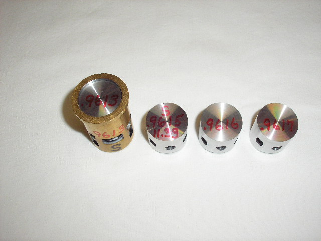
Piston OD is the same as the liner ID Notice in this photo the piston goes to the very top of the liner. Its OD is the same as the ID of the liner at the top. A motor fitted like this will run, but will not make any serious HP. Either one of the two pistons in the middle will be good to use in this liner. To determine the correct size of a piston for any tapered liner; first, measure the liner top & bottom carefully; second, check for roundness at these points; third, check at different points above the exhaust for roundness & taper to the top of the stroke. Out of roundness at the bottom has no effect. Liners with insufficient taper CANNOT be fitted properly with the correct crunch point! Four, add .0005 to the liners dimension at the top & cut this dimension on the piston's OD. Last, cut the top taper to achieve the correct crunch point. The total length of the top taper should be about .100 to .110 in long, measured from the piston crown. If the piston's top taper becomes to long, very small amounts (.000025) should be taken from the piston's OD. Engine manufacturers machine large numbers of pistons & liners, then select parts that will give the correct fit.
When you fit a piston you mention "crunch" numbers, in other words where the piston stops in the bore. I've always found this very subjective depending on how hard you push and the taper in the sleeve. Is there a more precise way to fit a piston? Possibly making the O/D match a certain size at some point in the liner? Ideas?
Looked at this sequence in your gallery but still wondering?
Piston OD is the same as the liner ID Notice in this photo the piston goes to the very top of the liner. Its OD is the same as the ID of the liner at the top. A motor fitted like this will run, but will not make any serious HP. Either one of the two pistons in the middle will be good to use in this liner. To determine the correct size of a piston for any tapered liner; first, measure the liner top & bottom carefully; second, check for roundness at these points; third, check at different points above the exhaust for roundness & taper to the top of the stroke. Out of roundness at the bottom has no effect. Liners with insufficient taper CANNOT be fitted properly with the correct crunch point! Four, add .0005 to the liners dimension at the top & cut this dimension on the piston's OD. Last, cut the top taper to achieve the correct crunch point. The total length of the top taper should be about .100 to .110 in long, measured from the piston crown. If the piston's top taper becomes to long, very small amounts (.000025) should be taken from the piston's OD. Engine manufacturers machine large numbers of pistons & liners, then select parts that will give the correct fit.
Last edited by a moderator: