You are using an out of date browser. It may not display this or other websites correctly.
You should upgrade or use an alternative browser.
You should upgrade or use an alternative browser.
Hard Industrial Chroming of Aluminum, Brass or Steel Cylinders
- Thread starter Jim Allen
- Start date


Help Support Intlwaters:
This site may earn a commission from merchant affiliate
links, including eBay, Amazon, and others.
Jim Allen
Well-Known Member
- Joined
- Jun 7, 2005
- Messages
- 1,622
I will begin chroming some Q-500 & Q-40 big flange sleeves next week. I'll explain, with photos, how the use of 2 PVC holding fixtures; 4 brass inserts & one chroming tank, easily makes it possible to chrome 6 sleeves within an 8 hour period.
JA
JA
Jim Allen
Well-Known Member
- Joined
- Jun 7, 2005
- Messages
- 1,622
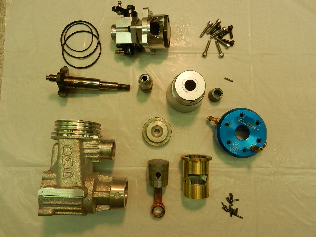
The four cylinders in the photo were recently returned for re-honing & re-fitting of new pistons with new heads. New heads must be fitted because the re-honing process will make the bore's ID larger. The use of loose fitting heads in any engine's cylinder bore will cause the engine to experience detonation! These used cylinders come to us with round bores (+ or - .0001") after many hours of WOT running. We believe the roundness is maintained because of the large, thick, type flange design. Notice the extremely high finish of the used cylinder bores. This finish is honed, not ground! The cylinders can be re-honed many times before they become scrape because only .0002" to .00025" of chrome/side will be removed during re-honing. The use of a Sunnen Gage ensures that the original bore roundness & bore taper amount is maintained.
Jim Allen
Jim Allen
- Joined
- May 18, 2008
- Messages
- 345
Jim,
Can you share the type of stones you're using, grit, compound, etc, and how you're setting the taper on the honing mandrel?
Can you share the type of stones you're using, grit, compound, etc, and how you're setting the taper on the honing mandrel?
Jim Allen
Well-Known Member
- Joined
- Jun 7, 2005
- Messages
- 1,622
Great Questions Brian,
I'll take photos with detailed explanations of how the Sunnen honing machine can be used to make very precise taper amounts while making those tapers round within + or - .0005". The process is known as "back honing" & standard Sunnen honing stones are used. The only special tool required is the simple holding fixture used to grip the cylinder's OD during the internal honing process. A fine grade Scotch pad is used to remove any stains left from the chroming process & to clean all the OD surfaces of the cylinder, while the cylinder is locked on the honing mandrel. The cylinder's OD & ID surfaces are throughly washed clean with a 50% solution of Dawn Dishwashing Liquid & Greased Lightening.
Jim Allen
Last edited by a moderator:
- Joined
- May 18, 2008
- Messages
- 345
Jim,
Would it be possible to make a brief video of the honing process? Also, Do you plateau hone the liner as you approach your final bore size?
Would it be possible to make a brief video of the honing process? Also, Do you plateau hone the liner as you approach your final bore size?
- Joined
- May 18, 2008
- Messages
- 345
Jim,
Question on your post #146 in regards to maintaining cylinder roundness, you stated you could maintain roundness within +/- .0005 and wanted to confirm it wasn't +/- .000050 given the resolution on the Sunnen gauge you showed in one of your posts.
Question on your post #146 in regards to maintaining cylinder roundness, you stated you could maintain roundness within +/- .0005 and wanted to confirm it wasn't +/- .000050 given the resolution on the Sunnen gauge you showed in one of your posts.
Jim Allen
Well-Known Member
- Joined
- Jun 7, 2005
- Messages
- 1,622
You are correct Brian. I have 2 Sunnen gages that I use. The gage permanently mounted to the Sunnen honing machine reads in .0001" increments. There is approximately 1/8" beetween each .0001" mark, therefore any movement less than .0001" can be easily read. I also have available a Sunnen gage that reads in .000050" increments. We found that the use of the latter gage is unneccessary for this measurement. Many times when the finish honing process is completed, the .0001" gage's neddle doesn't move as though its broken! All the Sunnen gages at Aero Precision Machine are owned by the company; they are not leased!
Jim Allen
Jim Allen
Jim Allen
Well-Known Member
- Joined
- Jun 7, 2005
- Messages
- 1,622
Brian,Jim,
Would it be possible to make a brief video of the honing process? Also, Do you plateau hone the liner as you approach your final bore size?
I'm thinking that a video of the honing proces from begining to end would not be of much help, since the proper "back honing technique" requires some time praticing to a point where a cylinder can be finished honed in 7 to 12 minutes. Keep in mind that the high production rate we have in the honing process is a direct result of a well designed & well controlled chrome tank, which plates only the exact amount required. I also have designed a simple holding fixture which makes it easy to hold the cylinder & prevent it from rotating during the honing process. A 7 mill rubber glove improves the grip on the honing oil covered holding fixture allowing it to be stroked back & forth while rotating under the pressure of the honing stone. Notice that the honing stones have been shortened from 2.5" to 1.9" for honing cylinders that are 1.480" in length. This is done to prevent a lip from forming at the ends of the stone. A very important part of the honing process is to "KEEP A CONSTANT ADEQUATE AMOUNT OF PRESSURE" on the cylinder's ID while the cylinder is stroked in & out! Failure to do this will result in a bore that is out of round! It should also be obivious why the large OD size of the honing fixture is a must! The fixture prevents the slippery cylinder from rotating, howerer it DOES NOT clamp down on the OD of the cylinder. Notice the set screws which opens the split fixture to allow the cylinder to slip inside. The white nylon screw sits in the exhaust window preventing the cylinder from rotating.
Only Sunnen MB-30-5 honing oil is used. The first stone used is a K20A61 (roughing stone); then a K20J83 (finishing stone). The taper automatically will come on the stones because of the machined taper in the cylinder's bore, that has been chromed & is also tapered. It is also possible to make small changes to the total taper amount (.0001" to .0003" on the total bore size) by adjusting the areas in the cylinder where the honing is being done. An understanding of how a very small increase or decrease in the amount of taper can only be determined by testing. Without the use of a Sunnen gage, accurate measurement woud be impossible! The cylinder's bore can only be measured from the top of the bore to the top of the exhaust window because of the open port windows.
When cylinders are returned for re-honing a K20J95 stone is used. We use this stone for rehoning because it greatly extends the life of a used cylinder. The finish it gives can only be described as spectacular! The photos show all of the things described in this post.
Jim Allen
Last edited by a moderator:
- Joined
- Jul 24, 2002
- Messages
- 7,130
Very interesting stuff Jim, thanks for sharing.
Can you tell us approximately how much chrome is worn off when a cylinder comes back for reconditioning? Does it all wear near the top of the sleeve? Is the sleeve still round or does it wear oval shaped?
What about the piston? Does it wear oval shaped?
Thanks again.
Can you tell us approximately how much chrome is worn off when a cylinder comes back for reconditioning? Does it all wear near the top of the sleeve? Is the sleeve still round or does it wear oval shaped?
What about the piston? Does it wear oval shaped?
Thanks again.
- Joined
- May 18, 2008
- Messages
- 345
Jim,
Thank you for the information. Looking at your photos, in regards to shortening the stone length, it looks like the length reduction is split and taken equally off of both ends of the stone?
Thank you for the information. Looking at your photos, in regards to shortening the stone length, it looks like the length reduction is split and taken equally off of both ends of the stone?
Jim Allen
Well-Known Member
- Joined
- Jun 7, 2005
- Messages
- 1,622
Terry,Very interesting stuff Jim, thanks for sharing.
Can you tell us approximately how much chrome is worn off when a cylinder comes back for reconditioning? Does it all wear near the top of the sleeve? Is the sleeve still round or does it wear oval shaped?
What about the piston? Does it wear oval shaped?
Thanks again.
The amount of ware on the chrome cannot be measured. This is because the plated chrome surface is as hard as possible (1100 + Vickers). The ware is taken up by the silicon (30%) in the piston's aluminum. In the past cylinders were honed with a cross hatch pattern because engine builders thought that the scratches would hold lubrication. What we discovered is that the cross hatch pattern doesn't help the lubrication & it greatly increases piston ware. It also made piston fitting to the cylinder a "BLACK ART". Actually the silicon is harder than the chrome plate, however there is only 30 % of it in the RSP-444 aluminum alloy.
When I measure a high amount of wear at the top of a cylinder, I know that the engine has been over leaned, over heated & the cylinder's aluminum base metal ( # 4032 aluminum) is blown out at the top. Even these cylinders can be rehoned to the correct taper amount & correct finish. All of our pistons & cylinders remain round through out their service life because of the thick, large diameter, cylinder lip design used on our engines with the bolts going through the cylinder's lip, not outside of the cylinders lip. The piston also remains round & evidence of this has been shown in previous photos. Bolts mounted outside of the cylinders lip are an engineering design mistake!
Lubrication between the piston & the cylinder's walls in our engines is maintained with the taper cut on the top OD of the piston. This taper cannot be filed or sanded on the piston's top OD as suggested by some engine experts! Grooves, even those that are wedge shapped, are useless in a high performance racing engine that may be running in an over lean condition. Engine pistons & cylinders that have been returned for rebuild, after running 10 laps at WOT, in an extreme over lean condition are round & they never show any signs of scuffing!
Jim Allen
Jim Allen
Well-Known Member
- Joined
- Jun 7, 2005
- Messages
- 1,622
Thats is correct. We cut through the stone down to it's base with a hack saw blade & then snap it off with a pair of vice grips.Jim,
Thank you for the information. Looking at your photos, in regards to shortening the stone length, it looks like the length reduction is split and taken equally off of both ends of the stone?
JA
- Joined
- Jul 24, 2002
- Messages
- 7,130
Again, thanks Jim.
So the chrome doesn't actually wear it's just that the top of the liner "blows out" when it sees to high a temp (lean).
Interesting the piston & liner wear round with your setup, I haven't measured my CMB's (lately) but I'm quite sure just by looking at the wear pattern on the piston the exhaust side goes away first.
Short of making a new sleeve with the head bolts going through the lip as you do is there any other way to hold the sleeve round at operating temps? Would making a tight fitting (light press fit) brass ring that fit the top of a CMB liner help?
Last edited by a moderator:
Jim Allen
Well-Known Member
- Joined
- Jun 7, 2005
- Messages
- 1,622
Terry,
Take a look at the posted photo & the explanation. Something smilar to this may keep things rounder in the top upper cylinder area. The wear pattern on the exhaust side of CMB should not be there because this engine is a rear exhaust design. A side exhaust engine might have this problem if the cylinder taper amount was high. Consider the fact that any piston rocking from side to side will always be in line with the connecting rod's swing. The crank pin & the wrist pin keep the piston from rocking in the other direction. Maybe the fixture used to bore the cyinders bore & the crankshafts bore is not square? Maybe there is to much clearance in that uncaged roller assembly on the bottom end?
Jim Allen
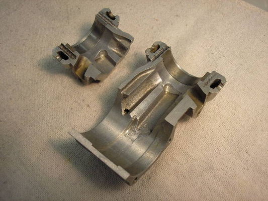 Stock OPS 67 crankcase The steel ring shrunk into the upper crankcase seat area for the liner lip to sit on can be clearly seen. Also notice the front end was threaded & bolted to the crankcase. This crankcase from a 1978 OPS 67 is the only stock motor I ever tested on the dyno. It produced 5.8 to 6.2 HP on 65 % nitro at 24,000 rpm. Every part in this motor was broken at some time!
The steel ring prevented the liner from crushing the lip in the crankcase.
Take a look at the posted photo & the explanation. Something smilar to this may keep things rounder in the top upper cylinder area. The wear pattern on the exhaust side of CMB should not be there because this engine is a rear exhaust design. A side exhaust engine might have this problem if the cylinder taper amount was high. Consider the fact that any piston rocking from side to side will always be in line with the connecting rod's swing. The crank pin & the wrist pin keep the piston from rocking in the other direction. Maybe the fixture used to bore the cyinders bore & the crankshafts bore is not square? Maybe there is to much clearance in that uncaged roller assembly on the bottom end?
Jim Allen
The steel ring prevented the liner from crushing the lip in the crankcase.
- Joined
- Jul 24, 2002
- Messages
- 7,130
Thanks Jim, I think I might try a ring around the sleeve lip...
TK
TK
Jim Allen
Well-Known Member
- Joined
- Jun 7, 2005
- Messages
- 1,622
Terry,
I didn't mean to imply that the ring solved any problem's in the upper end of the engine except to prevent the cylinders small flange from crushing the edge it was sitting on. The ring also did not eliminate the upper cylinder bending problem when the 8, 8-32 bolts were tightened to spec. A thick enough cylinder wall, typically .100" thick, a cylinder flange 1.875" dia X .200" thick, with 8 bolts passing through the cylinders lip into the crankcase, completely stabilized the cylinders upper areas; even when operating at the elevated temperatures found in the upper cylinder areas. This design also greatly improves the necessary cylinder, head, piston cooling that will become absolutely necessary during an over lean run.
One engineering change that will greatly decrease piston rocking is to raise the wrist pin hole to the maximum height possible. Since ABC or AAC engines have no piston rings, the connecting rod can be lengthened to the maximum. The connecting rod in the photo has no bushing in the upper end which allows it to be lengthened even further. This lengthening decreases the connecting rod's angle at the 90* & 270* points. This also means the forces acting on the rod & piston are reduced at the 90* & 270* points. The piston's total weight is reduced because the piston bosses will become shorter in length.
Jim Allen
Last edited by a moderator:
Jim Allen
Well-Known Member
- Joined
- Jun 7, 2005
- Messages
- 1,622
I have received several questions concerning the use of the cylinder's holding fixture (cylinder & cap), which slips inside the brass sleeve in the PVC outer shell. Making the two pieces shown allows for different size cylinders to be chromed in the same fixture. The top of the cylinder's holding fixture & it's cap should be machined then lapped as flat as possible. #360 free machining brass should be used for all the brass parts. Other brass alloys will work but may not clean up as well during the stripping process in the HCL bath. Each fixture is used once to decrease the stripping time. In the 6 th photo, notice the relieved area shown on the ID of the cylinder's holding fixture. This .020" deep relief in areas behind the cylinder's ports will be necessary to allow easy removal of the cylinder after chroming is complete.
Jim Allen
Jim Allen
Last edited by a moderator:
Jim Allen
Well-Known Member
- Joined
- Jun 7, 2005
- Messages
- 1,622
I have received several requst about the possibility of chroming various size cylinders. The standard cost of chroming a cylinder is approximately $50.00. This would include the finish honing process but does not include the cost of the various sizes of holding fixtures required. There is also the problem with removing the chrome from aluminum cylinders which can only be done by grinding the chromed surface down to the original aluminum surface. Removing chrome from brass involves placing the brass cylinder in a 50% solution of HCL. Therefore, from a cost consideration, the possibility of chroming anything except the production cylinders used in our engines would be out of the question at this time.
Jim Allen
Jim Allen
Last edited by a moderator: