engine timings

Intlwaters

Help Support Intlwaters:

This site may earn a commission from merchant affiliate links, including eBay, Amazon, and others.
Again you need to look at the whole picture and realize intake and exhaust durations are just part of the picture and going with overly long durations can lead to a slower engine due to a lack of ability to pull the prop off the beach.

As an aside, I found it interesting the in kart racing one of the international classes was for a single cylinder 100cc engine with exhaust duration limited to 177 deg and that was in place for decades. Engines in that class peaked at 14,000 rpm in the 70's and 80's. In the 1993 homologation, the new engines were able to rev to 17,000 rpm. By early 2000 when the 100cc class was replaced with a 125cc class, the engines were turning 20,000 rpm. The only significant change in the port layout was going from a dual exhaust port, two transfers and a single boost to a configuration of single large exhaust with two small side ports above the transfers, two transfers and a single boost.

So with what might be considered relatively mild port durations, i.e. exhaust in the +/- 180 deg range, tremendous power can be developed in a two stroke, but that requires proper development of how air and fuel flows internally in the engine as well as balancing out the transfer and boost durations, and the intake opening and closing.
 
A good amount of valid informaton has been posted here in regards to what timing changes could possibility effect. When considering a single cylinder two stroke racing engine, once the engine's RPM's exceed the time areas numbers available, even when unloading the engine & turning the engine faster, it will not make a HP increase. In the case of a single cylinder racing engine, gas or nitro, increasing the bore without an increasing the stroke will not produce the HP increase it should because increases in the bore size have little effect on increasing time area numbers.

After building many single cylinder racing engines with different bore stroke combinations, It became apparent to us that a longer stroke, smaller bore engine can produce more HP than a short stroke, big bore engine of the same displacement. The mechanical benefits of the long stroke, small bore design have not been mentioned.

Jim Allen
 
It seems that with the kart and motorcycle two stokes, the Japanese and Italian engine builders run pretty close to a square setup, i.e. bore and stroke are the same. For the 100cc,s a nominal 50mm bore and 50mm stroke and for the 125's a nominal 54mm bore and 54mm stroke though the values varied by a few tenths between manufacturers. For gasoline engines there were fairly well developed with the 100cc's making 35-40 hp @ 20,000 rpm and the 125's making 45-50 hp @ 14,000 rpm. A lot of R&D development went into the design of those engines, especially the 4 cyilinder 500cc GP bike engines.
 
If you look at the pictures I posted you can see the wire method I use. Fixed head engines are tougher than removable sleeve engines to measure. The hooked wire in the first picture fits into the exhaust port to measure the transfers. The 45 degree method in the second picture gives a system to measure radiused exhaust ports. A radius on the exhaust and piston as shown in the attached pictures greatly improves the flow in the early opening phase of both exhaust and transfers.

Lohring Miller

attachicon.gif
exhaust edge radius.png
attachicon.gif
piston edge radius.png
I will share a trick with you for measuring the transfer duration on a fixed head open port engine. It takes all the chances for error out and it is so simple.

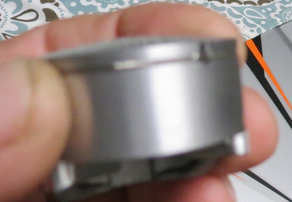
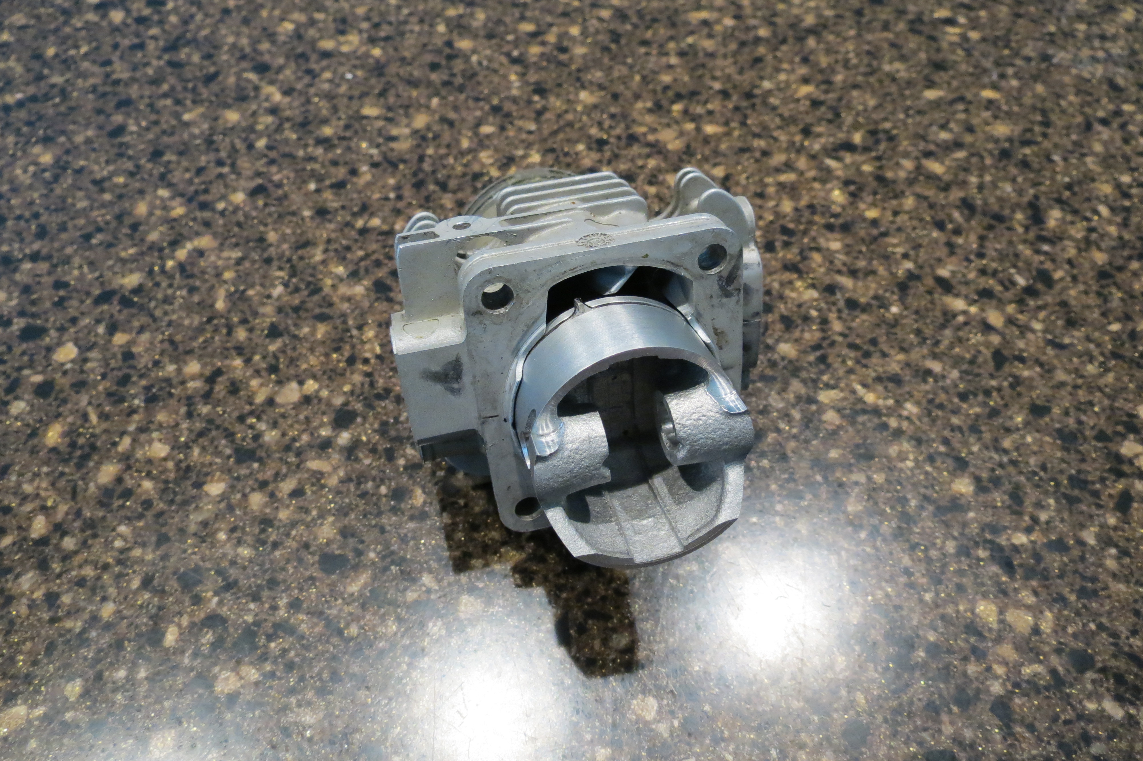
This is a tool I made to make it easy to check transfer duration.

It is a partial ring almost half with a tab silver brazed to the edge of the ring with the exact same height as the piston crown. You simply place it in the ring groove and guide it up the open transfer and it rides right up to the roof of the transfer and acts as your piston stop so you can rotate until it hits again and you got your exact dead nut accurate reading of your transfer duration with no chance for error. The same tool works in 34 or 36mm pistons because they are exactly the same distance ring to crown and since it is a partial ring it fits them both the same.

Excuse the blurry pictures. The camera was focusing on the background.

PAO8hjs.jpg


NA3CFuY.jpg
 
Last edited by a moderator:
No it isn't in or touching the bore it is installed with the tab located in and is going up the open transfer port on a fixed head cylinder.

Timing degree wheels are as or are more accurate than feeding a program a bunch of measurements. Make even the slightest error on ten different measurements needed to feed a program and you really can make a mess of some port work. Measure with a large diameter degree wheel and starting at zero and measuring the duration is dead nut accurate with zero chance for error. Your not designing the engine you are modifying it and it can be done very successfully. Yes it is so much more than timing numbers but you learn what shapes and sizes work just as fast as with any other method.

A degree wheel, a stop bolt and a dial indicator mounted over the stop bolt you can know exactly where any amount of adjustment will take the timing too and be able to mark the bore with a scribe on marking dye and start cutting.

Slice up a piston like the one I am using with the ring/tab and it will allow nice straight scribe lines to cut up to.

zoyf2zX.jpg
 
Last edited by a moderator:
Have noticed that NR is designing in that direction, at least on some of their engines.

The physics is obvious on the under square theory, IMO.

tw
i have been running N/R Car engines(.21 &.12's) with longer stroke for 20 years now and they seem to have to best power and power band of any of the engines i have ran.
Agreed.
 
Building & modifying piston ported racing engines doesn't involve only the precise measurement of the cylinders's timings. All of the windows involved have both radial & axial angles which can greatly effect the gas flow in & out of the engine, even if the timings are correct. How does the bore's size, the thickness of the cylinder's wall, the radial & axial angles of the windows effect what is happening to the gas flow? How do you determine what angles are best? Is there an EPA program or computer program that gives the answer? A racing engine needs to be a very efficient air pump! More fuel can be delivered by opening the needle valve!

The photos below show some of the scaled up drawings (some at a 1 to 20 ratio) used to build connecting rods, retainer assemblies, cylinder windows & basic timing numbers. A scaled up drawing can be used to determine accurately any engine's timing. The key pieces of information needed are, the connecting rods center distsnce, the engines stroke & the distance from the wrist pin's center to the outer edge of the piston crown. The only tools needed are a measuring scale, a compass, a protractor & some .100" square graph paper. Notice how a scaled up drawing can show small details. It can also be used to determine many of the necessary measurements in question.

Jim Allen
 
Back
Top