Jim Allen
Well-Known Member
- Joined
- Jun 7, 2005
- Messages
- 1,622
Tim,
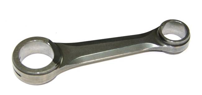
I do not think that it is always necessary to use a steel, roller type, connecting rod in a .46 size engine. Consider the fact that the connecting rod used in the MB-40 engine is aluminum (7075-T 651) & it is only bushed in the bottom end. This engine operates in the 33,000 to 35,000 RPM range. I'll post some detailed photos of the connecting rod & the inside of this unique engine when I return to the shop.
JA