- Joined
- Feb 17, 2005
- Messages
- 512
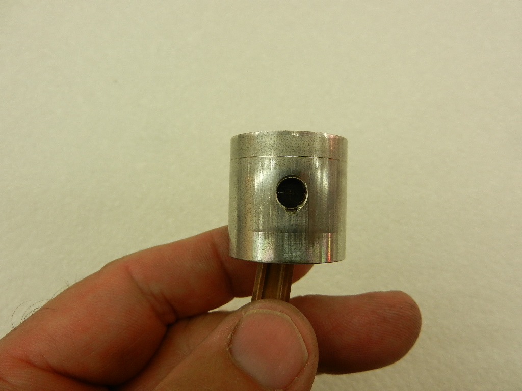
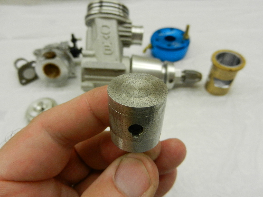
Jim, can you explain why the first piston is not what it should be?
It has a nice even wear/sealing ring near the top.
It has a nice even wear/sealing ring near the top.


Mike,hey jack or jim,could you go a little into stinger size and length and the effect it has on piston wear. I notice that my on-road car engines from nova rossi that come with pre made pipes and headers that the piston wear is more even then in some of the boat engines I have seen.thanks,mike.
Ken,Jim, can you explain why the first piston is not what it should be?
It has a nice even wear/sealing ring near the top.


Whats up Mike,On the tuned pipe volume measurements, how are you measuring it? Are you filling the pipe with water and measuring the amount of water?
Also what is being considered for the "ends" of the pipe? Is it the end of the header and the end of the stinger?
Thanks in advance.
Mike

Terry,
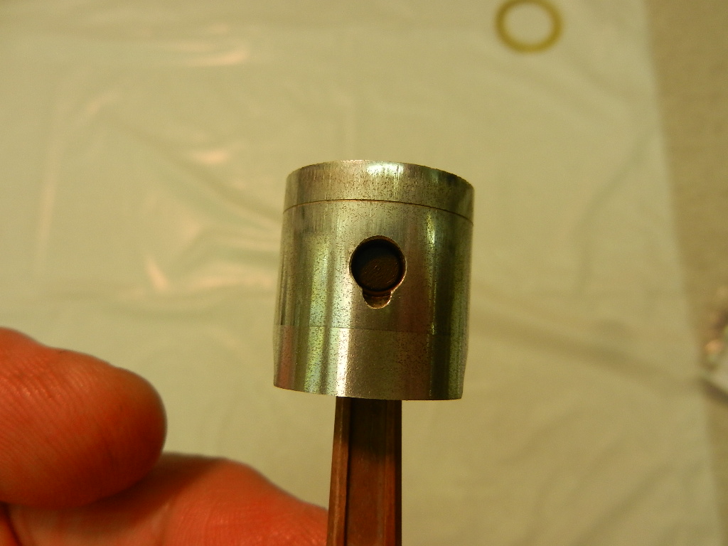
I'm sorry for missing your #14 post referring to the MB engine, which clearly shows the necessary wear band & its position in relation to the piston's crown. Rob Metkemeijer, Henry Nelson & I have had many discussions about this "Wear Band" when they visited the Julian air races. Any AAC or ABC engine that does not have this will rapidly lose it's piston to liner fit, & therefore it's peak HP over a very short period of time. I have witnessed MB 40 FAI speed engines routinely operate at 35,000 RPM in the air while maintaining their piston to liner fit.
https://fiorimet.hom....nl/Running.htm "This should be done very lightly & carefully, especially at the "ring", approximately 2.5 mm (.0984") from the top of the piston where it seals."
Jim Allen


Rudy,Jim, do you know of any chemical that would dissolve a steel bolt from an aluminum case, leaving the aluminum alone? Rudy
Jim, do you know of any chemical that would dissolve a steel bolt from an aluminum case, leaving the aluminum alone? Rudy
Enter your email address to join: