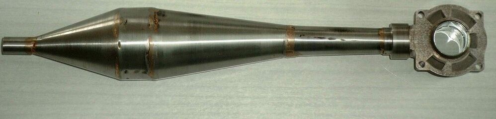
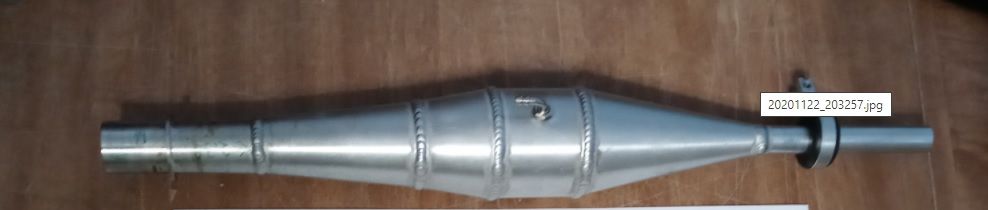
Thanks again for that, I'll definitely be tapping into that resource when I have some good data to work with. I see right away our pipes need improving when I look at the MB 40 pipe:
Wonder if Scott Bouchie was using EngMod2T? Hmmm...
Right again, there's not a lot of info for glow engines, and if there is it's for FAI fuel. Adding 60-80% nitro to the mix probably changes things a bit, lol.
Can I ask you again?
"When you guys were running your 67's on the dyno how exactly did you set the needle? Did you just kinda just know where it should be from on the water testing? How did you cool the motors? Did you monitor EGT's or CHT's?"
I'm trying to figure out how to set the needle so it's just slightly rich of peak before doing a dyno pull, I could see how a motor would easily go over-lean as the wheel is taking time to spin up. I was thinking of running my fan unit with a particular setup to find a good needle first, then switching to the dyno wheel but that's a lot of work going back and forth. Maybe watching EGT and CHT will help?
Making a pull, leaning the needle, rinse and repeat seems like a recipe for disaster on a dyno...