Run in stand/dyno build.

Intlwaters

Help Support Intlwaters:

This site may earn a commission from merchant affiliate links, including eBay, Amazon, and others.
Pin now 0.200" with flats, up from 0.160". Also saw that Speedmaster had 5/16" collets and nuts so I upped the shaft size while I was at it.


full
 
Last edited:
Terry, I assume it is to allow more angular misalignment between the two parts and reduce wear on the pin. When the drive pin is free to rotate along its own axis it will self align to the flats in the female coupler. When the pin is locked, the flats rock instead of slide and will wear into the sliding surfaces. Your set-up is pretty close to dead nuts aligned so hopefully it's not an issue, but I suspect with engine vibration, crank flexing, etc, you will see some more wear compared to if the pin were floating. Just my 2 cents.

-Tyler
 
Think I'm ready for the dyno wheel finally. The large R12 bearing that holds the female U-joint was fit too tight and the cheap Flee-bay oilers were causing problems, both fixed and now she's smooth as silk.

My buddy Rudy said it would be cool to see some slow-mo video to see how the crank moves around...

 
Last edited:
Did an initial test of my fan setup, not easy running a motor indoors in the suburbs, lol.

Camera angle is bad on the video but you get the idea.


full


I gotta vent the Byron fan away from the exhaust fan, won't be a problem with the dyno wheel of course.


Last edited:
Did an initial test of my fan setup, not easy running a motor indoors in the suburbs, lol.

Camera angle is bad on the video but you get the idea.


full


I gotta vent the Byron fan away from the exhaust fan, won't be a problem with the dyno wheel of course.


John Bridge used an automotive muffler mounted in a basement window, replaced the glass with sheet metal.
 
One thing about it that fun is getting well lubed.Terry That pipe is that going to you bed room.LOL
 
This is a great thread full of some great info, I have been trying to figure out how I can build a dyno for my hydro engines and this will help a lot. Thank you.

I do not run RC hydro's at the moment and instead, I run tethered hydro's. - I have not read every part of this thread but saw that you had issues with couplings failing, This is something I have had while running tethered hydros but I have recently been using the below design and so far it seems very promising.

C1.jpg

C2.jpg

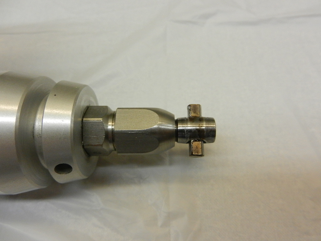
This is just the first prototype and for this, I used a 1/5 scale RC car CV joint (This is from a FG Marder) its just case hardened steel that I cut in half and drilled to take a 1/8 piano wire shaft. the balls are normal ball bearings and due to the specific tolerances once they are pushed in are able to rotate inside the bore without falling out.

The cup is silver steel, this was a prototype but I have since machined a hex on the outside so that I can tighten them onto the crankshaft. they are also hardened and tempered. For reference, the main bore of the cup is 12.5mm and the ball bearings are 5mm, OD is 18mm

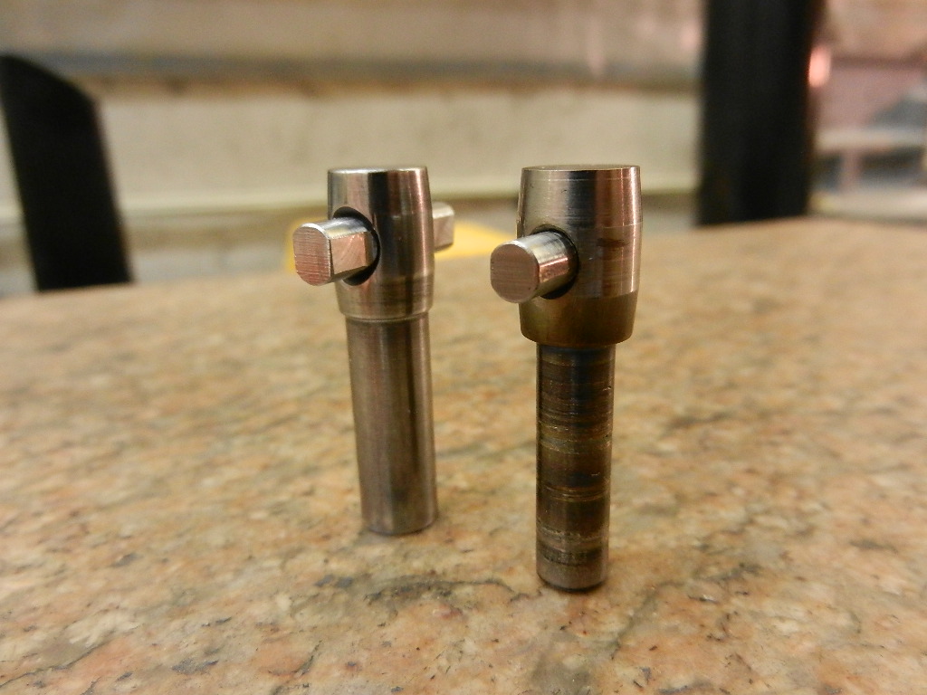
At the other end of the shaft, I made my own cup and skeg shaft - See below.

C4.jpg

C5.jpg

These are pictures of prototypes again but are useful for an explanation. The ID of this smaller cup is 6mm and the balls used are 2.5mm, literally half the size of the other end. Again, once machined the cup and skeg shaft are hardened and tempered.

I have used this on a .60 Picco speed powered hydro with no issues at all so far though I am still trying to perfect the tolerance for the ball fits on the smaller shaft.

By design, this is a very balanced set up with very little slop/play compared to the more usual single pin through a ball design that is typically used.

Regards

Ricky
 
Very interesting, I never saw a connector like that before.

Can I ask what coupling(s) you were running? Where did they fail?

What part of the world are you in that still runs tether boats?
 
Very interesting, I never saw a connector like that before.

Can I ask what coupling(s) you were running? Where did they fail?

What part of the world are you in that still runs tether boats?

The couplings we use in tether hydro’s are normally all bespoke home made designs but are very similar to what you have shown above. They often fail at the in that goes through the ball much like yours did. We have also had some of the cups fail as well.

I am based in the UK, we still run competitive tethered hydro’s. We often compete in Eastern Europe countries as they are also still running tethered hydro’s and very competitively as well.

The euros/worlds is mostly held in Bulgaria now but we have competitors from all over the world.

We utilise some interesting props and engines. Here are some pictures for reference.

2750897E-B444-48AE-88E3-C2A1C758424F.jpeg
A91BC3D4-51E7-4DB4-B9FE-7DBA9A59DC49.jpeg
5842C217-A858-40E3-9448-9B551C1E37EE.jpeg
264236BA-340E-4FDC-8E2C-5A0811EB85D1.jpeg
A3B68104-DB8B-4971-933C-3802FB31F498.jpeg
 

Latest posts

Back
Top