Dumas Miss Circus Circus Pipe Mounting Tips

Intlwaters

Help Support Intlwaters:

This site may earn a commission from merchant affiliate links, including eBay, Amazon, and others.

the german

Well-Known Member
Vendor
Joined
Apr 21, 2008
Messages
502
Hey Guys

any good idea how to mount the tunedpipe in a 1/8 Dumas Miss Circus Circus.

Would be nice if anyone post pics

Thxs for help

Alex
 
If you're using a rear radio box, I would try to run it out through the turbine pipe. I know that would make access to the radio box harder, but it's about the only way to hide the pipe and clear the box
 
If you're using a rear radio box, I would try to run it out through the turbine pipe. I know that would make access to the radio box harder, but it's about the only way to hide the pipe and clear the box

I am using a rear radio box and i want to run the pipe trough the turbine pipe. Now i'm looking for a good solution to hold the pipe inside the turbine pipe.........any ideas?
 
One thing I've seen done to make removing the radio box lid easier was to screw a bracket to the box lid and fasten the pipe to the bracket with an automotive hose clamp. If you can weld, you could fabricate a bracket, weld it to the pipe and screw it to the box lid with slotted screw holes to allow for adjusting the pipe length later
 
I don't have any pictures of how I mounted mine, but it worked ok. I cut a disc from 1/8" fiberglass sheet slightly smaller then the ID of the tube. Slit a piece of w/washer tubing and glued it around the perimeter for a tight fit, but could still be removed. Cut a hole in the center of the disc and installed a high temp grommet that just fit around the exhaust pipe. It was basically a friction fit, but worked pretty well. Ended up using a bit of silicone to help hold the disc in place in the turbine tube, and drilled a few 3/8" holes in the disc to increase airflow. When I built my second one, I mounted the radio box forward and ran it out the transom.

winston 013A.jpg
 
I don't have any pictures of how I mounted mine, but it worked ok. I cut a disc from 1/8" fiberglass sheet slightly smaller then the ID of the tube. Slit a piece of w/washer tubing and glued it around the perimeter for a tight fit, but could still be removed. Cut a hole in the center of the disc and installed a high temp grommet that just fit around the exhaust pipe. It was basically a friction fit, but worked pretty well. Ended up using a bit of silicone to help hold the disc in place in the turbine tube, and drilled a few 3/8" holes in the disc to increase airflow. When I built my second one, I mounted the radio box forward and ran it out the transom.

One thing I've seen done to make removing the radio box lid easier was to screw a bracket to the box lid and fasten the pipe to the bracket with an automotive hose clamp. If you can weld, you could fabricate a bracket, weld it to the pipe and screw it to the box lid with slotted screw holes to allow for adjusting the pipe length later
Thnxs guys for the ideas !


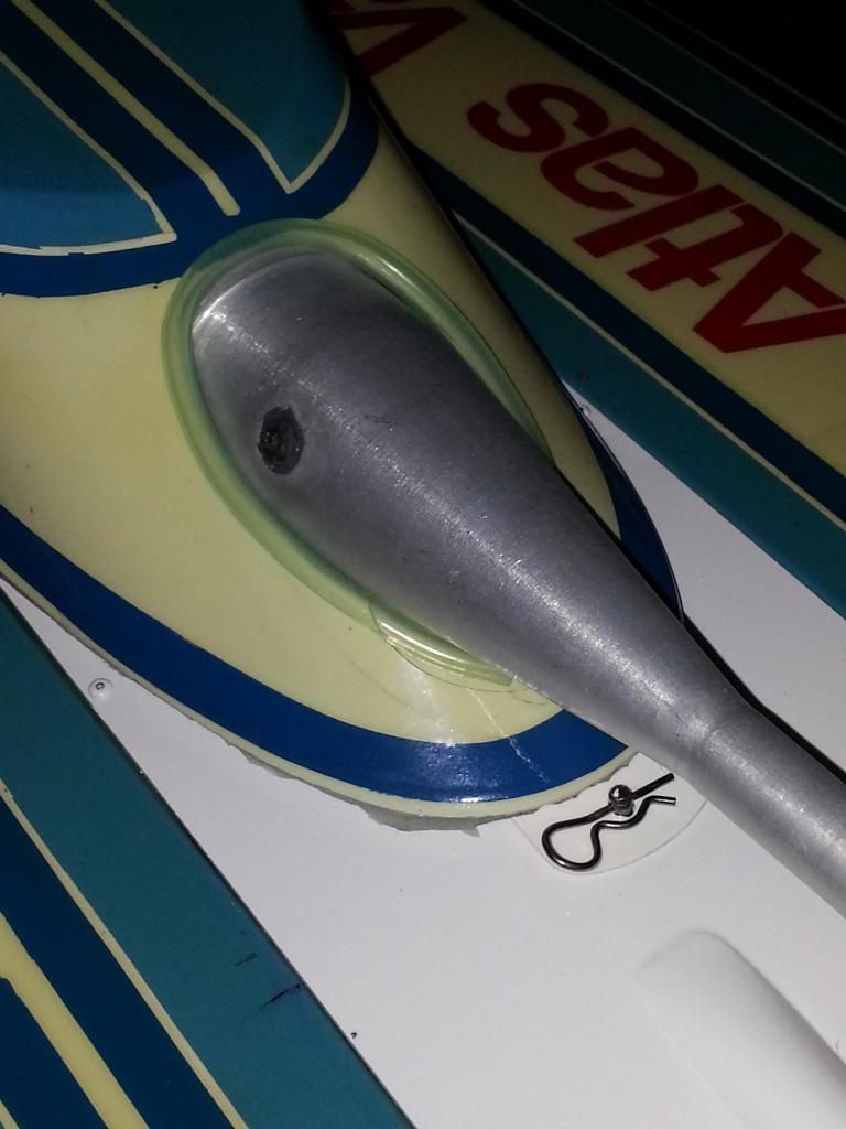
How it was done on this used Atlas i have and it kinda touches on what Micheal posted. Different size fuel tube,,to hold different sized pipes firm. Slit the tubing and squeeze it over the inside disk edge, slide the pipe in the center Allow for adjustment as you build it. Auto hose clamps to hold pipe to engine and coupler,, and cross your fingers. Looks like a inverted entry or? slammed the cowl and crushed the old pipe against the 1/16 ply,,and it did. Fixed for now.

I would use something larger than 1/16 plywood for your mount ring. A heavier plywood or fiberglass, Like Micheal posted.

You are dealing with heat and weight as you build and I would keep that in mind..

Ease of entry into and clearance of the pipe to radio box lid is Important also as you already know.

Hope this helps.
 
NOT a legit scale Keith, pipe needs to exit thru transom or be concealed by a cowl.
 
here's a simple bracket i made based on ideas shared by Dave Brandt..

glued threaded brass insert into a bulkhead, made a strap with slot to slide pipe in/out, made another strap that goes around stinger

if you want to run it thru the turbine tube, adjust it upward and cut a slotted hole in the bottom of the tube

20141010_111936.jpg
 
Last edited by a moderator:
Cowling is in 2 sections and the pipe mount is glued to the bottom of the hull with a good epoxy glue and chopped fiber for strength. The pipe is joined at the header using a teflon pipe coupler these never burn out and are very rigid. This bot is well over 15 years old.

DSC00029.JPG

DSC00028.JPG

DSC00026.JPG

DSC00027.JPG
 
I used tuned pipes like the CMB AB67 muffled pipe, then had a support clamp around the muffled section as closed to the centre of the cone of the pipe as I could get, that clamp was mounted to the floor of the hull, and then put the rear deck with turbine tube in place first then then when I mounted the pipe mount to the floor it held the whole lot in place. Sorry no pictres, because I just changed it so the pipe exits the transom. Somebody said it was better that way.
 
forgot to mention that although my bracket holds the pipe by the stinger, I would probably secure the pipe differently if it were a cmb/black thin walled pipe, people on this site have mentioned those pipes breaking at the welds? from vibration? (bob "har har" johnson tipped me off and makes cool pipe brackets that hold the body of the pipe)

the muck pipe is thick walled aluminum with fat welds that seems ok secured at the header and stinger
 
Last edited by a moderator:
i know this will be to late but i'm working on some thing ill try to update in a couple weeks once I have it nailed
 
I'm building the Winston Eagle Lobster and face the same issue with hiding the pipe. I'm going to use a center of the hull mount for the pipe which is rear exhaust RCMK, then the tube will be slotted to fit around mount and pipe.. Mounting the tubing is now a question but since I'm going with stainless adding mounting tabs shouldn't be hard to figure out?? I know this don't help much but I'm thinking out of the box myself!!

Later!!

Pat
 
Don't know how to Post pictures on here but i used 3mm carbon fiber strip 3/4" wide the full length of the tube glued some 3/4"x3/4" X3mm pads on the ends rounded them to match the tube ID, Drilled .112" holes in the tube from the underside & marked the CF pads drilled & tapped the CF for 4-40, figured out where the Speedmaster pipe support needed to be to allow adjustment & marked it. Removed drilled & mounted the mount. The backside of my Radio box is contoured to clear the pipe & then a small foam support sits at the front of the pipe behind the coupler on the radio box lid. Its all hidden except the couple inches of paint pen tube extension to bring it flush with the back of the tube. If any one wants to explain how to get pictures posted Ill try.
 
Back
Top