[SIZE=12pt]Looks like you have a good start.[/SIZE]
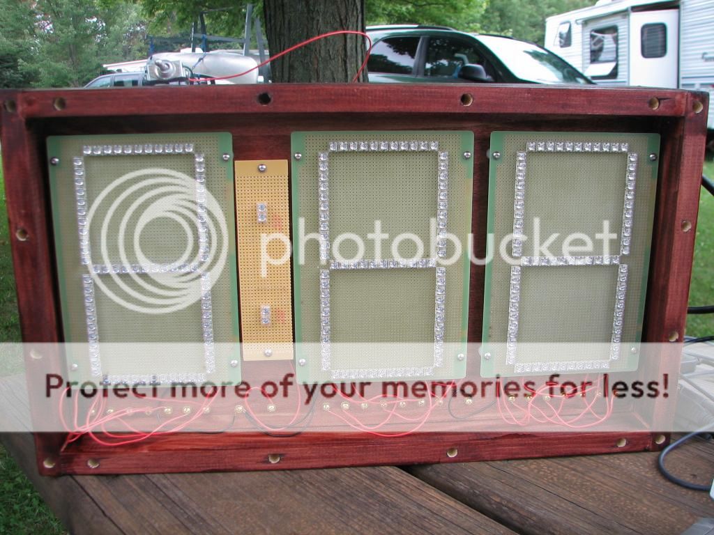
[SIZE=12pt]Have you read what the IMPBA Rule Book says about digital starting clocks? It talks about clock operation, digit size and color.[/SIZE]
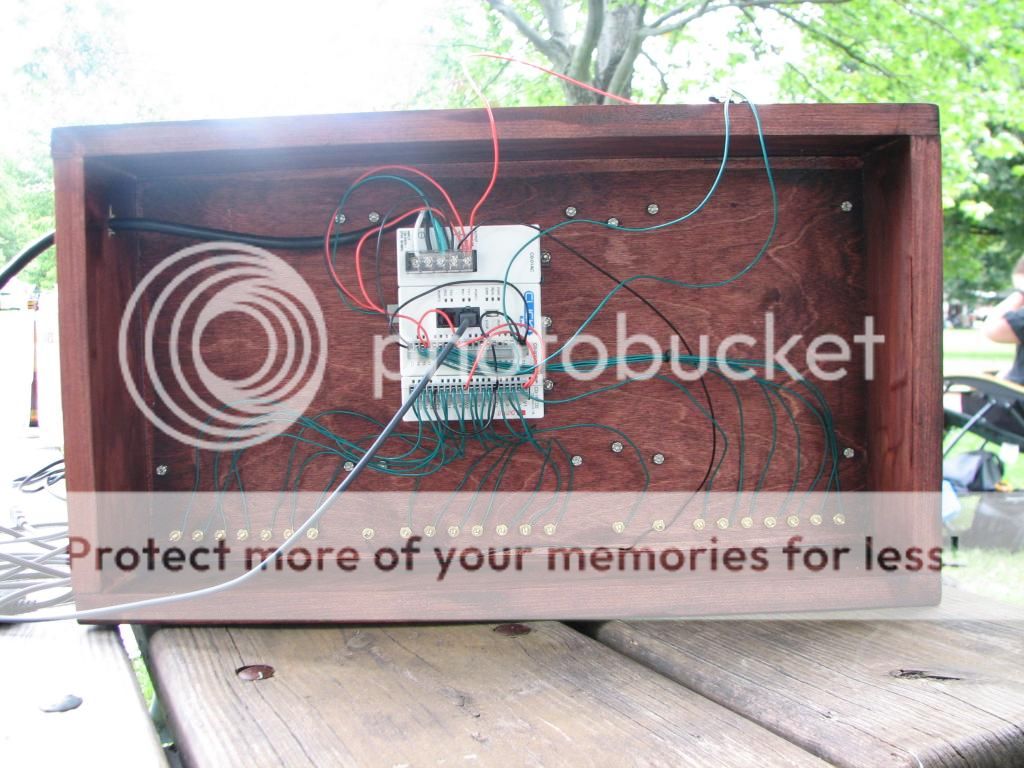
[SIZE=12pt]I have worked with this type of PLC Controllers used on production lines. They will do some strange things when they are operated outside their comfort zone. Their max operating temp is 140 deg F. and[/SIZE] a humidity range of 30 – 95 % (non-condensing). What might work in New York might not work in other parts of the country.
[SIZE=12pt]After years of designing and building electronic circuits, I have learned, if possible, to always use components that are rated at least 105 deg C. and that are not sensitive to humidity changes.[/SIZE]
[SIZE=12pt]DonB[/SIZE]