Need some CAD help?

Intlwaters

Help Support Intlwaters:

This site may earn a commission from merchant affiliate links, including eBay, Amazon, and others.

Terry Keeley

Well-Known Member
Supporting Member
Joined
Jul 24, 2002
Messages
7,124
Want to run some Autodesk CFD testing for a new SAW boat. I need to draw the model and import it into CFD using one of these programs:

http://help.autodesk.com/view/SCDSE/2016/ENU/?guid=GUID-47E4ACDE-45E3-4FFB-B771-15B2EFD2E974

I've only heard of Inventor and Solid Works and am leaning towards Inventor since it's also an Autodesk product but any insight into either?

I'm a (near) total newby to CAD so ease of use is important!
default_smile.png
 
Terry,

Inventor and SolidWorks are both 3D CAD programs. I have only looked at Inventor but use SolidWorks regularly. I have also done what you are referring to with drawing up a hull and using a CFD program evaluate.

On the question of is one easier to use than another - I cannot really answer since my experience is only with SolidWorks. For SolidWorks, once you get the concept of solid modeling understood, it is then a matter of learning the program commands. Learning curve is not "hard" but long at times - if that makes sense. There are now lots of online videos that help too. Solid modeling is used for items like engines, hardware, etc. More of your basic flat surface type items.

For modeling "curvy" shapes like some boat hulls, surface modeling gets used. This becomes harder and more frustrating at times. Each surface has to be drawn in 3D space. Once all the surfaces are drawn, they have to form a "watertight" object with no gaps/holes where surfaces meet. Once done, the object is converted from a surface model to a solid model and is ready for a 3D program. Probably not the best description but hopefully you get the idea.

For the CFD part, I use SolidWorks Flow Simulation. There is a learning curve with CFD and I am no expert. Programs are becoming easier to use with more examples available, tutorials, setup wizards, etc. With CFD programs you can do 2D and 3D analysis. Just depends upon what you are after. 3D takes longer to run a simulation.

Luckily I have access to SolidWorks and the CFD program through my work. The cost of each program is pretty significant. Same with the Autodesk products. Both offer educational versions at a much lower cost - if you are student.

Be glad to answer any questions.

Mike
 
Thanks much for the reply. Doing a little more digging I see that Autodesk Simstudio Tools that is installed with CFD can be used to import a drawing from Autocad (I have Autocad 2013).

Just messing around making a 2D side profile of a hull and trying to convert it to 3D, I drew it in "2D wireframe" which has X & Y axis' but when I try to extrude it to 3D the side profile is really the bottom. I need to either re-assign Y to Z or extrude from the side view.
 
Terry,

When working in 3d it all about how you are "viewing" the part. Once you draw it in 2d, extrude it in 3d and then you can use the rotate command to either rotate it 90* to make it a side. Example would be you would be in your isometric view when you extrude the part to be 3d. You then need to mess with your USC Control. This will change how you can rotate the part. If you changed your USC Control to left you could rotate your part to make a side..... not Sure I did a good job explaining this.... maybe a video would help.

Sent from my SAMSUNG-SM-G930A using Tapatalk
 
I have done quite a bit of Surfacing in SolidWorks. It is a pain to get the hang of, but once you do, it is only time consuming after that. Haha. I like to use hand drawn sketches, bring them in as sketch images on each plane, "trace them", and then make surfaces.
 
Terry,

When working in 3d it all about how you are "viewing" the part. Once you draw it in 2d, extrude it in 3d and then you can use the rotate command to either rotate it 90* to make it a side. Example would be you would be in your isometric view when you extrude the part to be 3d. You then need to mess with your USC Control. This will change how you can rotate the part. If you changed your USC Control to left you could rotate your part to make a side..... not Sure I did a good job explaining this.... maybe a video would help.

Sent from my SAMSUNG-SM-G930A using Tapatalk

Thanks, that's what I'm seeing. I found a really good set of tutorials for a newby like me, she's become my new BFF!

https://www.youtube.com/playlist?list=PLvFYwxhh980YgD3_Zsfhi7HAJGjkf5X7b

https://www.youtube.com/playlist?list=PLvFYwxhh980al4B9oihpZWompt_xrVAmn

I was able to draw a profile, join the lines, extrude it to a solid, now I'm playing with USC to get it oriented right...
 
Last edited by a moderator:
You can use the command bpoly to join all your lines in 2 clicks to make life even easier. Have fun!

Sent from my SAMSUNG-SM-G930A using Tapatalk
 
Terry,

I suspect I know what you are trying to accomplish and I am afraid your efforts will result in a dead end. I don't mean to dissuade you, but I have been down this road my with SAW boat.

Assuming you are trying to look at lift and drag with ground effects you need something 100X more powerful than what Floworks or the equivalent AutoDesk product can handle.

I have designed all my boats in Solidworks and had a Floworks license where I tried to simulate the lift and drag characteristics. The challenge is you need an open flow environment, i.e not flow through a closed system like modeling coolant flow through a heat exchanger. If you intend on adding ground effects this adds another massive chunk of computational horsepower. My workstation said it would take over 300 days to compute the coarse modeling with no iterative loops.

I showed what I was trying to do with a colleague who does nothing but race car aerodynamics. He bluntly told me for the data I was looking for I needed the same computational horsepower as what the high level Cup, Indy and F1 teams are using. He humored me and loaded my model into Ansys, set-up the conditions and asked the computer to estimate the processing time with a cluster server dedicated to CFD. About 1 week for the basic results at an alarming high 5 figure cost for the cluster time.

He turned me onto Foil Sim from NASA. You might consider this first before investing in a CFD solution. https://www.grc.nasa.gov/www/k-12/airplane/foil3.html

-Tyler
 
Last edited by a moderator:
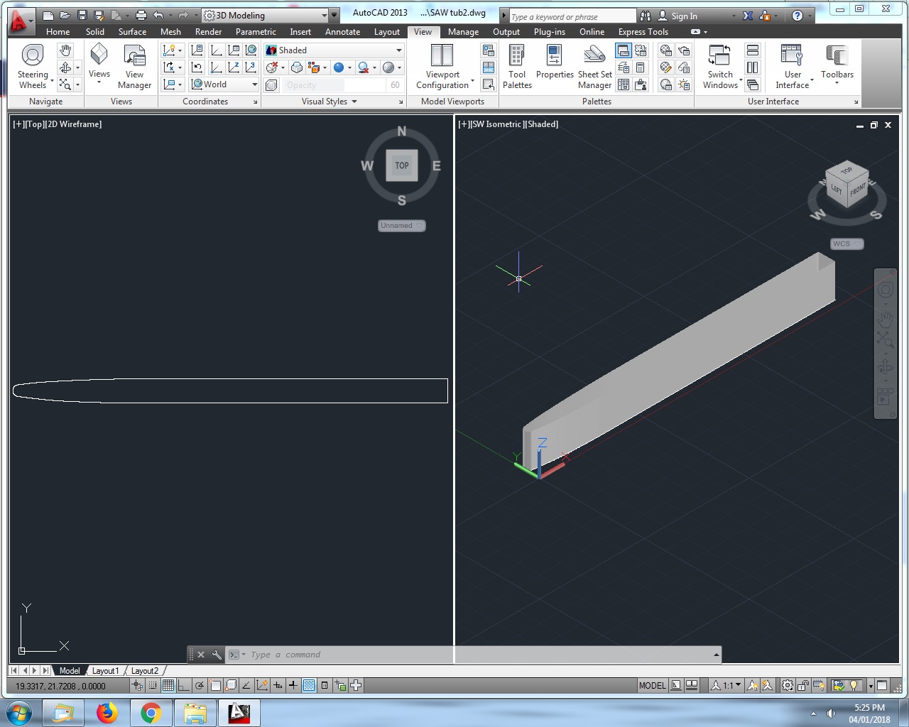
Well I drew a basic tub shaped thing, joined the lines to one polyline, got the co-ordinates right in USC and extruded it into a solid 3D object. That's enough for one day.
default_laugh.png


Last edited by a moderator:
Terry,

I suspect I know what you are trying to accomplish and I am afraid your efforts will result in a dead end. I don't mean to dissuade you, but I have been down this road my with SAW boat.

Assuming you are trying to look at lift and drag with ground effects you need something 100X more powerful than what Floworks or the equivalent AutoDesk product can handle.

I have designed all my boats in Solidworks and had a Floworks license where I tried to simulate the lift and drag characteristics. The challenge is you need an open flow environment, i.e not flow through a closed system like modeling coolant flow through a heat exchanger. If you intend on adding ground effects this adds another massive chunk of computational horsepower. My workstation said it would take over 300 days to compute the coarse modeling with no iterative loops.

I showed what I was trying to do with a colleague who does nothing but race car aerodynamics. He bluntly told me for the data I was looking for I needed the same computational horsepower as what the high level Cup, Indy and F1 teams are using. He humored me and loaded my model into Ansys, set-up the conditions and asked the computer to estimate the processing time with a cluster server dedicated to CFD. About 1 week for the basic results at an alarming high 5 figure cost for the cluster time.

He turned me onto Foil Sim from NASA. You might consider this first before investing in a CFD solution. https://www.grc.nasa.gov/www/k-12/airplane/foil3.html

-Tyler

Thanks much for the input, it's always good to hear from someone who's "been there, done that".

In Autodesk CFD they show several examples of cars etc. in simulated wind tunnels, I haven't dug deep enough into it yet to see what specific data is available but I'm not going to go too deep. I've been running a flat bottom on my past two boats and thought I'd try a curved aft section hoping to create some "free" down force at the transom, like a diffuser on a race car.

I did a bunch of poking around the net but couldn't find anything specific about shapes, angles etc. Obviously the higher the angle the more force - right up until the flow separates. I want to try and simulate just this bit for some direction.

Thanks for the Foil Sim link, I had looked at that before but forgot about it.

ps: The Autodesk CFD crashed my laptop just running the examples, lol.

edit: I got it launched into CFD from Simstudio!
default_smile.png
 
Last edited by a moderator:
Played with foil sim about 5 yrs ago. It is interesting to play with see what happens. May have to revisit it myself
 
My interest in 3D printing lead to the need to learn a 3D modeling program. Fusion 360 is free for hobbyists, so I took the plunge. There is a steep learning curve. YouTube has some very helpful videos. The ones by Lars Larson are the best I've found. I accomplished the first task of building a "program" that will draw any cleaver style propeller from 30 mm to 70 mm diameter with up to twice the diameter in pitch. The rake, cup, number of blades, and hub are also variable. Below are some examples. The next project is engine design.

Lohring Miller

62 x 140 prop.png 50 x 70 - 0 rake.jpg 40 x 56 - 20 rake.jpg
 
Last edited by a moderator:
OK, I've entered a bunch of individual points for the top side, I realize now I should have used the line command and drawn a line from point to point.

Been Googling for an hour, any way to join the points into a smooth line?

Tub.jpg
 
Glad your back on your feet again & out of hospital

Sent from my SM-N920V using Tapatalk
 
Thanks. When I select that or any other line command my cursor has text boxes for x-y values and I can't select my existing points?
type os then return to get the OSnaps menu, click the tick box next to node, then click OK. Now when you use the Polyline command you can select your points.

Yup, I found it finally! I didn't have the node option selected, should have the tub drawn tonight then it's off to the wind tunnel.
default_tongue.png
 
Any one have any idea how to rotate the drawing so it's on the "wall" instead of the "floor" in the SW Isometric view?

I can rotate the co-ordinates about the X axis but the drawing doesn't move with it, I should have started it that way.
default_sad.png


Tub2.jpg
 
Last edited by a moderator:
Back
Top